Posts: 337
Threads: 13
Joined: Apr 2019
City: Greenwood
State, Province, Country: Delaware
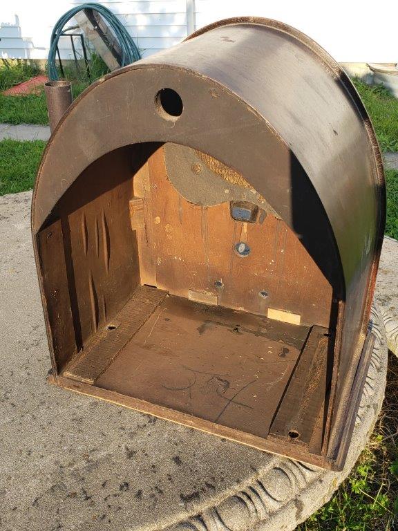
I'm grateful this forum is here, and I've enjoyed reading about Philadelphia Storage Battery Radios. I run across philcoradio.com while searching for information on an old cathedral my son bought. I cannot divulge how much he paid, but it was about a half a tank of gas including tax.
Since I'm not afraid of taking anything apart (and my parents never stopped me), I will attempt to get this thing running. My son (Ben) is working
on the cabinet.
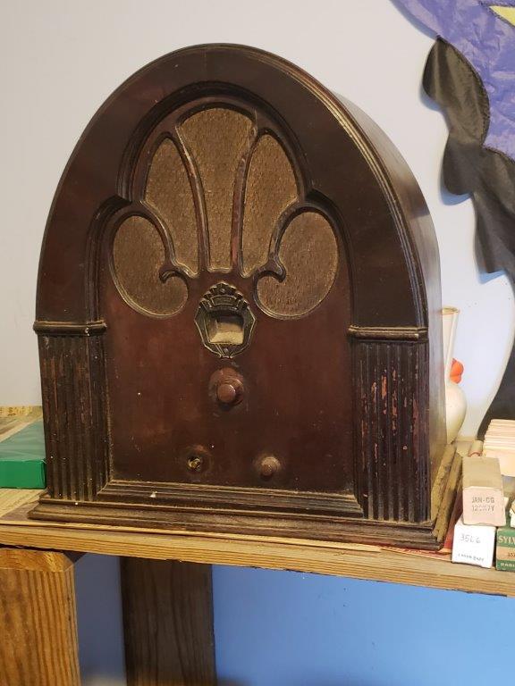
The article in 'Tech Section, 'Notes on Model 21' is especially helpful.
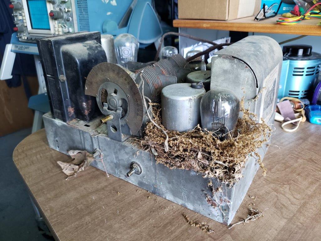
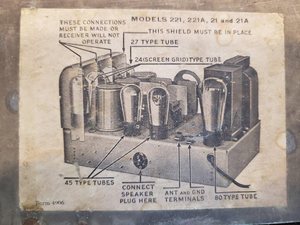
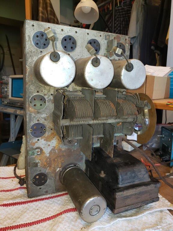
Tubes as found (the 80 and a 45 were in wrong locations when I drug it home)
1st RF, 2nd RF, and Detector- Philco type 24, Majestic G-24, and Philco 24A
1st audio Majestic G-27
2nd audio Wizard K9-45 and RCA Radiotron UX-245
Rectifier Cen-Rad 80
I can't test emissions, but all the heaters have continuity.
Notice the cabinet has 2 wood spacers shimming up the chassis. The left side of the chassis had slipped off one of them, and that's why the shafts were cockeyed in the front holes. I thought the shims were odd; and wonder if all 21's had this?
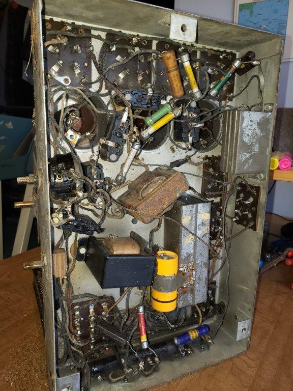
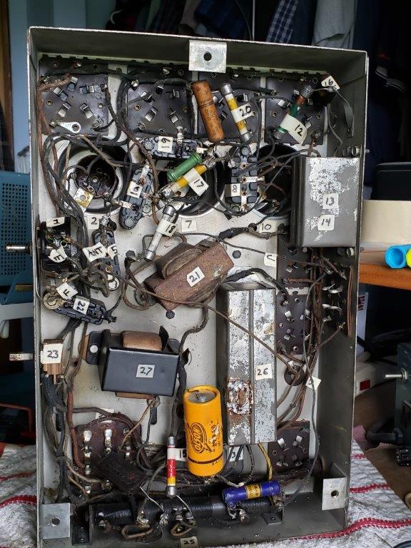
I stole a forum members technique, and labeled the components with masking tape.
Posts: 337
Threads: 13
Joined: Apr 2019
City: Greenwood
State, Province, Country: Delaware
Measurments taken in circuit Using old Radio Shack 22-221 VOM :
-Resisters-
-all the dogbones measure high; the Bakelite (8) measures 250 ohms. the BC (25) measures fairly close to spec and
there is blue resister added between 6-7 (I'm gonna leave that alone!). I see a green dogbone added in parallel to original(17).
Volume Control (1) (Ant-RF coil, 0-5000 ohms) jumps all over the place
-Transformers-
-Power Transformer (24) low to no resistance, except terminals 9-6 and 6-12 (1k), and 9-12 (340 ohms).
-Filter choke (27) measures 265 ohms
-P/P input (21) is obviously a replacement, as it is rusty, and has taped wire splices. measures 1000 pri 650-590 sec.
-RF coils (2)(7)(10) no resistance as measured.
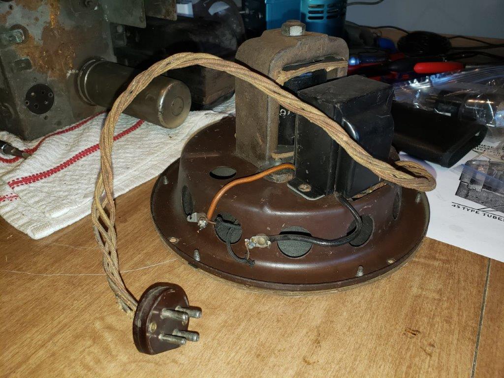
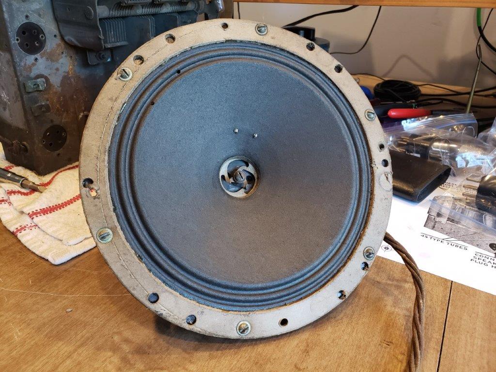
-Speaker field coil (J-D) measures 3K
-Capacitors-
-Electrolitic (31) is the big round can on top, Filter Condenser (26) is big rect. can underside, bypass (13 & 14) smaller cans
screwed to chassis back. The added Olson 'dry electrolitic' was to fix (31), I think. There is an .02 paper capacitor scabbed onto condenser (19 .01).
Plan of action:
1. take out the stuff that don't belong and make sure wiring is correct.
2. remove variable capacitor, bath in soapy water, and remove rust.
3. take out filter choke (21) and make it prettier. reinstall.
4. rebuild bakelite capacitors per Philco Library 'Bakelite Capacitor rebuild without Desoldering'
5. rebuild bypass cans and filter condenser can (use Solen)
6. replace dogbones with what? Carbon Composition?
7. fix/clean volume control (clean with 99.9@ alcohol only)
8. clean top of chassis/reinstall Var Capacitor
9. replace power cord (original wasn't that bad, but has frayed spots)
10. what else? I need all the wisdom from this forum I can get! I hate doing things twice.
11. Before any of this, order stuff I know I will need....
Regards,
Simon
Posts: 599
Threads: 8
Joined: Apr 2018
City: S. Dartmouth
State, Province, Country: MA
IMHO the extensive cleaning can and should wait. First determine if the power transformer is alive. Remove the 80 rectifier tube, examine the pilot light wiring for shorts. Tubes can be left in. Check the power cord for breaks that could short. Tape them up.
With the 80 out of the radio and all wiring associated with the power transformer in the clear but connected, power the set. The tubes should light, the transformer will fail almost immediately if it is bad or as long as 30 minutes. If the transformer is cool and no cracking, smoking after 30 minutes. The transformer is good.
Do not power the radio again until all restoration is completed.
Next check, rather, re-check the antenna and RF transformers. If any are open they must be rewound or replaced. The "Rule" is rewind as the Philco Ant. & RF transformers have celluloid layer insulation. This insulation decomposes and then corrodes the copper wire. There is no "solder-in" fix for this unless someone rewinds the coils for a hobby...
The final check is the volume control, ideally, the only check is an operating radio but if the control does not change resistance measured with an analog ohmmeter uniformly, it is likely "noisy" use a known control cleaner, not WD-40...
If the control is shot either a used replacement, again, iffy or a replacement from Marc Oppat. His specialty is controls and will have what you need.
Now clean and shine up, all the tough stuff is done...
There are a couple of procedures how to easily gut and repair the Bakelite block caps. Info on the web. These must be done as they are paper construction and are leaking.
Do take care of the 45 tubes, they are expensive to replace even for weak ones.
Do not re-route the wiring as changes could cause un-wanted oscillation. Replace any rubber covered wiring with similar size/type new plastic insulated.
YMMV
Chas
Pliny the younger
“nihil novum nihil varium nihil quod non semel spectasse sufficiat”
(This post was last modified: 06-19-2019, 08:21 PM by Chas.
Edit Reason: Spelling errors, clarification.
)
Posts: 7,213
Threads: 266
Joined: Dec 2009
City: Roslyn Pa
If you have a lot of patience you can make your own bed resistors https://www.radiomuseum.org/forum/replic...stors.html
When my pals were reading comic books
I was down in the basement in my dad's
workshop. Perusing his Sam's Photofoacts
Vol 1-50 admiring the old set and trying to
figure out what all those squiggly meant.
Circa 1966
Now I think I've got!
Terry
Posts: 1,393
Threads: 69
Joined: Oct 2007
City: Linn Creek, MO
Posts: 7,213
Threads: 266
Joined: Dec 2009
City: Roslyn Pa
+1! Was only a click or two away. Was looking for that but didn't see it.
When my pals were reading comic books
I was down in the basement in my dad's
workshop. Perusing his Sam's Photofoacts
Vol 1-50 admiring the old set and trying to
figure out what all those squiggly meant.
Circa 1966
Now I think I've got!
Terry
Posts: 337
Threads: 13
Joined: Apr 2019
City: Greenwood
State, Province, Country: Delaware
Chas, The power transformer is alive! Powered up slowly to 110v, and all the tubes (no 80, of course) heated up. Left it sit for 1/2 hr, and Pt is still cold. The '45' tubes are an odd couple; the 'Wizard' got a lot hotter than the Radiotron...
Coils- rechecked, All 3 (grid to ground) measure 4 ohms.
Primary (2) 20 ohms, (7) 11 ohms, (10) 11 ohms.
Pilot Light doesn't work. The bulb shows continuity, so maybe dirty connection or something....I don't see it on schematic.
Volume Control (5K ohms to coil) needs attention (no WD-40!), if no luck then Marc Oppat.
Resistors- there's only 5, so make my own? maybe!
-Simon
Posts: 337
Threads: 13
Joined: Apr 2019
City: Greenwood
State, Province, Country: Delaware
Pilot lamp is ok- it was was not making good connection in socket.
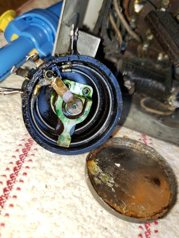
Removed volume Control, pried off the cover, and cleaned inside with 99.9% alcohol. It works much better! I think it will be ok.
Question- Now what to lubricate with? I have some silicone dialectic compound. I used light machine oil for the shaft bushing.
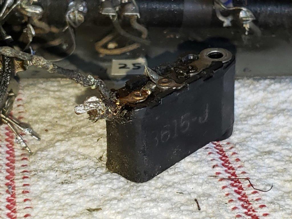
Bakelite capacitor-this is going to be easy! tar came out with a little heat- but check old soldering job on the one tab. And, there's more joints like that- not sure that's even solder!
-Simon
Posts: 337
Threads: 13
Joined: Apr 2019
City: Greenwood
State, Province, Country: Delaware
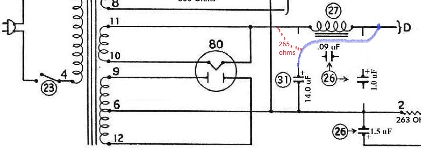
Update! Have repaired all the Bakelites, but I think Filter Condenser and Mershon (which was bypassed) is wired wrong. Filter Choke (27) one end goes to 11 on Power Transformer, other to D,(goes to Field Coil), which also is where Electrolitic (31) positive connects. I'm going to change that, and wire it per schematic unless somebody tells me different.
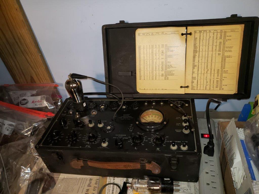
Aquired a tube tester I-177, had it repaird by hainc2bc; found 3 bad tubes- the 80 and of course the two 45's. In the market if anybody has a good deal.
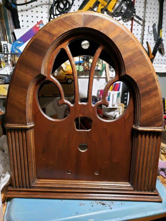
Sneak Preview of Cabinet! Ben is almost done with it. "Now we need a low humidity day for lacquer. Look ok to you?" I would say so, Son!
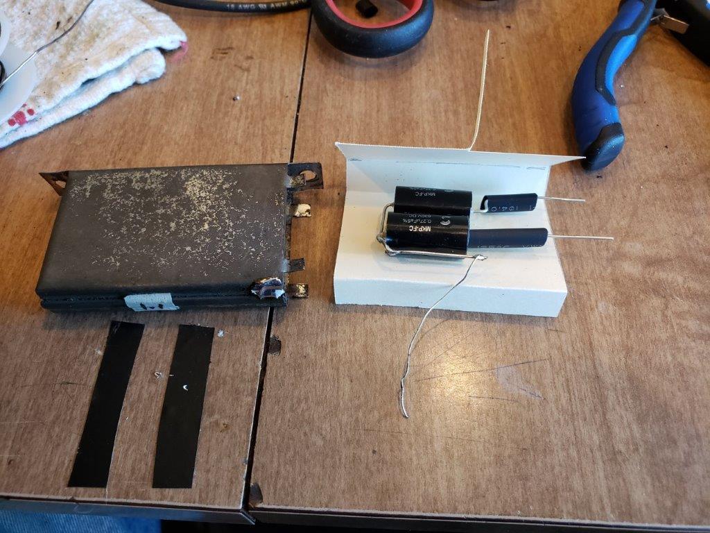
Here's one of the bypass condensers- they weren't too bad to 'stuff'- glued to paper carton and reuse the two end pcs.
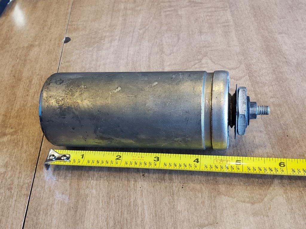
Ahhh yes, the Mershon. 2" dia. x 4.63" lg. still thinking on that one. Maybe tube cutter, and collar to fit inside.
Posts: 599
Threads: 8
Joined: Apr 2018
City: S. Dartmouth
State, Province, Country: MA
Quote:I'm going to change that,and wire it per schematic unless somebody tells me different.
That is fine but stick close to the values in the schematic. The filter is tuned to reduce hum rather than brute force.
IMNSHO Don't bother to stuff the Mershons. Install a tie strip under chassis to deal with all the leads and install axials or radials. That way if the hum is objectionable changing the value of filter cap after the choke will have a better effect. If the first filter cap after the rectifier is too high stressful for the rectifier and will raise the B+ which, because of higher line voltage will be higher too. Put the Mershons back in the chassis for show...
You may have to tinker with the back bias resistor for the 45's so they run just warm...
You did notice that inside one of the Bakelite blocks is a crude wire-wound resistor 
Were the RF/IF coils all measured for continuity?
GL
Chas
Pliny the younger
“nihil novum nihil varium nihil quod non semel spectasse sufficiat”
Posts: 7,213
Threads: 266
Joined: Dec 2009
City: Roslyn Pa
Psssst... Chas it's a trf set.
When my pals were reading comic books
I was down in the basement in my dad's
workshop. Perusing his Sam's Photofoacts
Vol 1-50 admiring the old set and trying to
figure out what all those squiggly meant.
Circa 1966
Now I think I've got!
Terry
Posts: 599
Threads: 8
Joined: Apr 2018
City: S. Dartmouth
State, Province, Country: MA
Just delete the "IF" all the same applies...
In another recent forum/post I helped debug a Philco 70, so conjoining similar Philco coil issues was in forefront.
Its the heat 
Pliny the younger
“nihil novum nihil varium nihil quod non semel spectasse sufficiat”
Posts: 337
Threads: 13
Joined: Apr 2019
City: Greenwood
State, Province, Country: Delaware
Chas, I did measure the RF coils:
All 3 (grid to ground) measure 4 ohms.
All 3 (Primarys) (2) 20 ohms, (7) 11 ohms, (10) 11 ohms.
I did find the bakelite with the 'hank' of wire in it, and I put it back along with the new capacitor. About went blind resoldering that fine wire, though!
yeah, I'm still thinking about that Mershon....Thanks Chas!
Posts: 337
Threads: 13
Joined: Apr 2019
City: Greenwood
State, Province, Country: Delaware
IT'S ALIVE !!
Could not get more than one distorted station before figuring out that signal is not getting to 1st RF coil due to malfunctioning 5000K section of potentiometer. will work on that, and post a video soon.
But here's some update pictures:
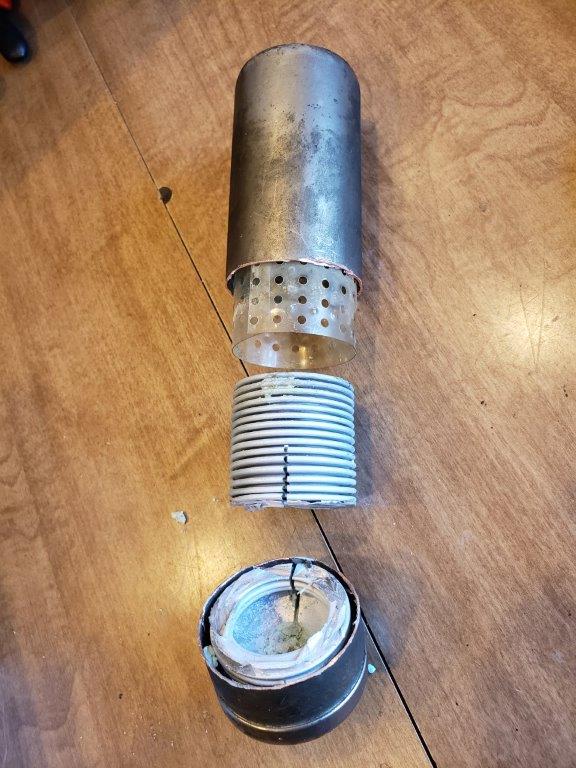
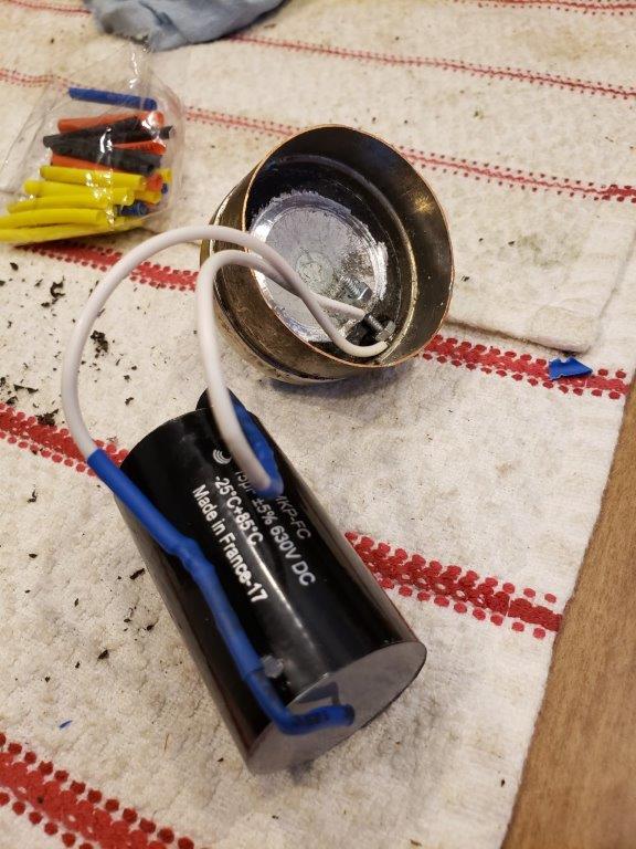
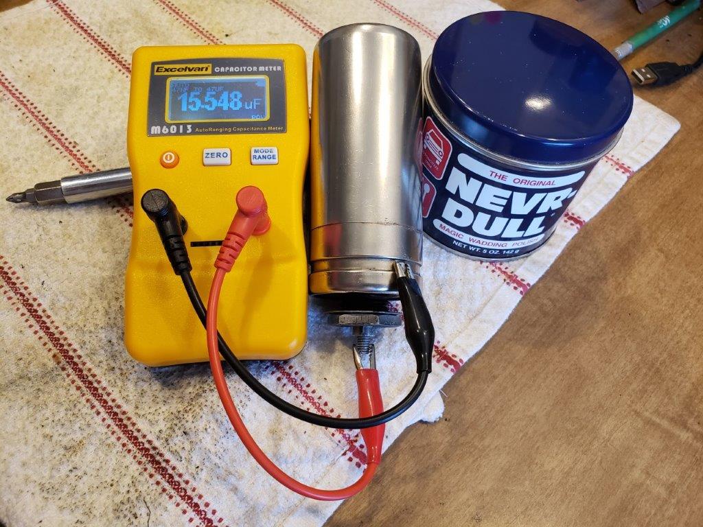
In retrospect, I would have parted the Mershon case in the lathe instead of a cut-off wheel, 'cause we used the lathe to separate the inside bottom anyway. A 1-1/4" PVC female pipe coupling split the long way now holds the case together.
I had to do it, Chas! I had to see what was inside!
I used 4-40 hardware to connect the new cap.
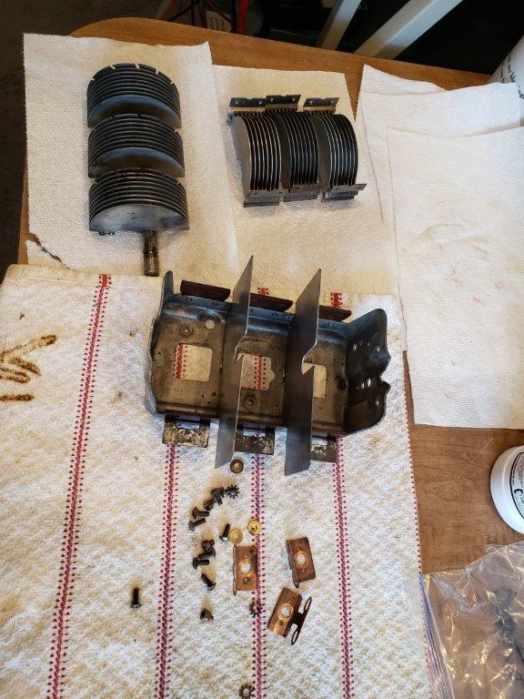
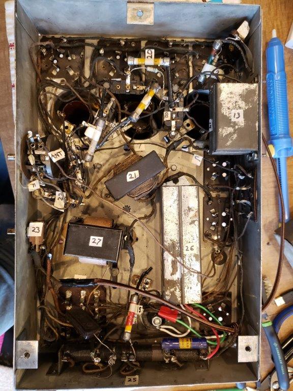
The resistors, I left them in! Just unhooked on side, and scabbed in modern ones; they are small, and really don't distract (I think!)
Posts: 2
Threads: 0
Joined: Apr 2019
City: Milford
State, Province, Country: Delaware
Looks good dad! The case is coming along. Holding pics until it is finished! 
Users browsing this thread: 2 Guest(s)
|


