Posts: 13,776
Threads: 580
Joined: Sep 2005
City: Ferdinand
State, Province, Country: Indiana
So I drilled the needed holes and installed two of the terminal strips needed.
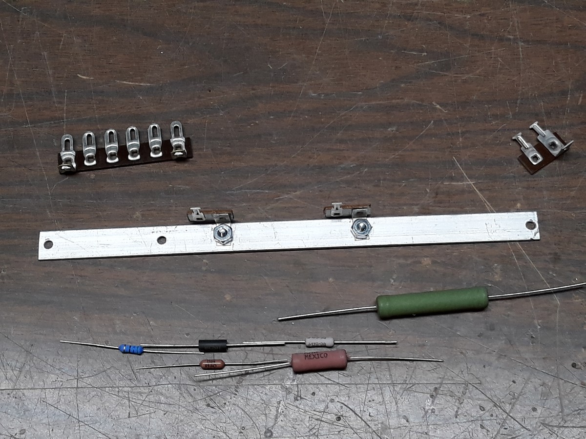
The aluminum strip was then installed on the back of the chassis.
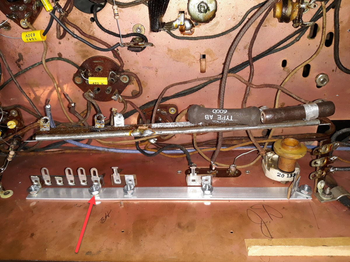
I had to drill an extra hole in back of the chassis to make a grounding point. I felt that would be better than relying on a solder blob, or running a long wire to a grounding lug. The red arrow points to where I drilled the extra hole in the chassis.
Then, with the strip in place, I moved the wires from the Candohm to the new assembly.
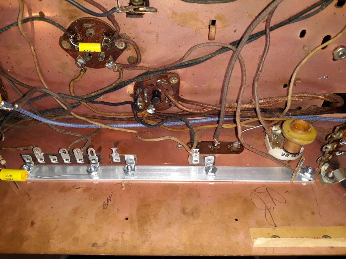
Notice how I mounted the terminal strip at far right at an angle. This was done to make sure it, and the 11K resistor, would clear the 456 kc wave trap.
And finally, I added the necessary resistors.
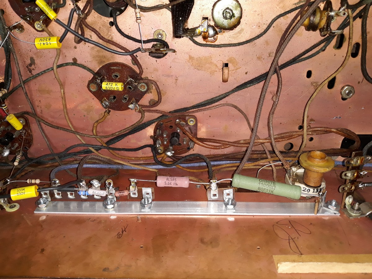
11K replacing the original 11K section
5.6K in series with a 60 ohm resistor to replicate the 5660 ohm section
86.6 ohm replacing the original 86 ohm section
56 ohm replacing the original 56 ohm section
250 ohm replacing the original 250 ohm section
So, that job is done!
I added a rubber grommet to the hole in back of the chassis through which the AC line cord passes through.
--
Ron Ramirez
Ferdinand IN
Posts: 13,776
Threads: 580
Joined: Sep 2005
City: Ferdinand
State, Province, Country: Indiana
Next, I moved to the 2nd 1st IF transformer. I needed to replace the wire lead on top which goes to the 6K7G grid cap as the wire obviously had crumbling insulation.
But when I removed the can shield, I found a surprise!
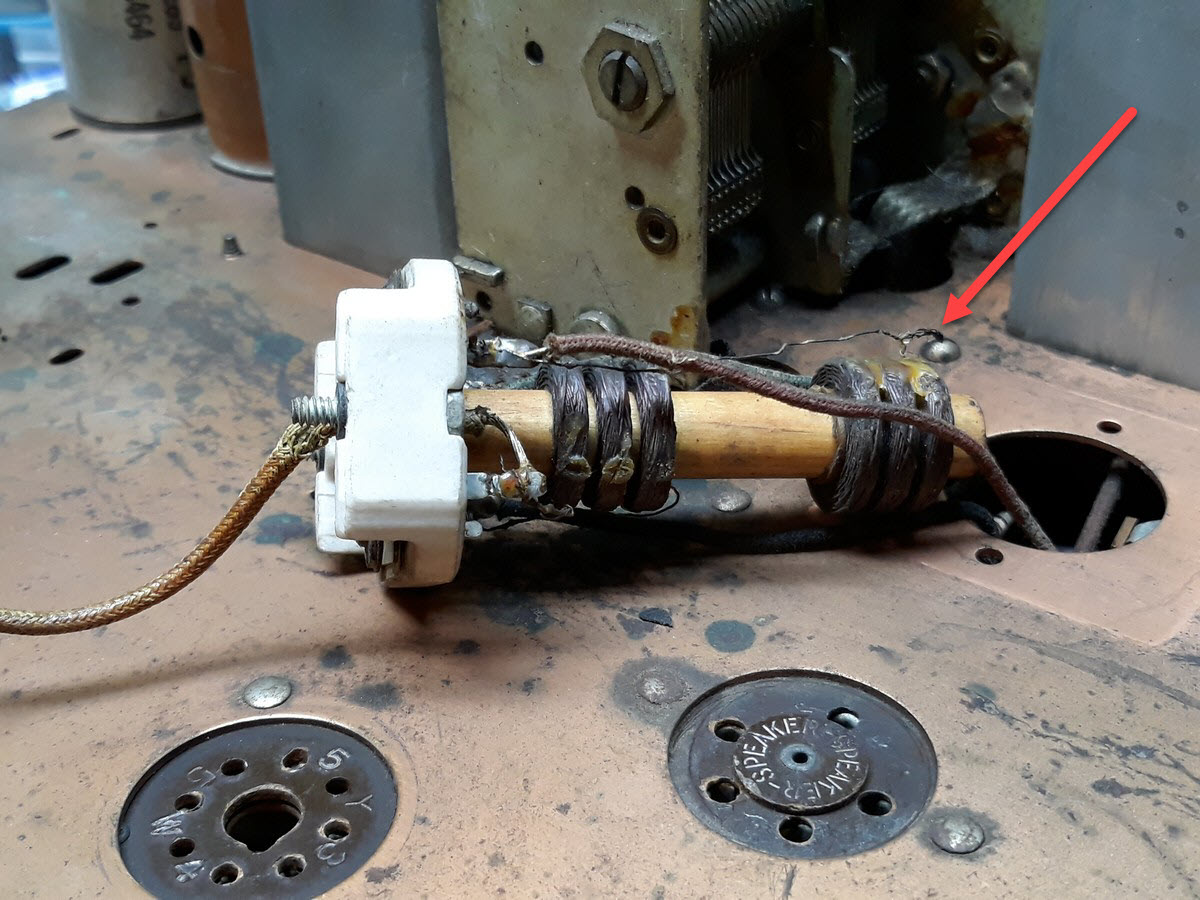
Look carefully where the red arrow is pointing. A thin wire is broken. Not only that, but the lower triple windings are very loose on the bobbin. And it is impossible to tell exactly how close (or how far) the lower windings were originally in relation to the upper windings.
Then I remembered...the seller had told me that a previous owner had recapped this set but it then would not play. Maybe this is why? In any event, I am glad I found this before I powered up the chassis only to be left wondering why it would not play!
I have a 1938 Zenith 6-S-2-something (6-S-254?) chassis out in the house garage which I had bought for parts a few years ago, in case I needed anything for a 9-S-262 chassis I hope to restore in the future. I think I will just use the 2nd IF from the 6-S-254(?) parts chassis...assuming that IF transformer is OK, that is.
But by now it was getting late and time to stop for the evening.
More tomorrow!
--
Ron Ramirez
Ferdinand IN
Posts: 1,856
Threads: 212
Joined: May 2015
City: Seattle
State, Province, Country: WA
Great progress Ron! And lucky find with the IF transformer!
Posts: 1,447
Threads: 96
Joined: Jul 2012
City: Poughkeepsie, N.Y.
Ron, Looking good I wish I had the know how to do all of that work on the radio. Will have to learn little by little after I retire and have the time to be schooled about this stuff. Thanks for posting the progress on the Zenith. And I hope you feeling well. 
Posts: 753
Threads: 48
Joined: Feb 2013
City: Shenandoah,
State, Province, Country: Pennsylvania
Looking very good Ron. A very thorough job indeed. I just wonder how you come across an 86.6 ohm resistor, hardly a standard value. Something that might be used in a VOM or some such piece of precision equipment!
Ron
Bendix 0626. RCA 8BX5. RCA T64
Philco 41-250. Philco49-500
GE 201. Philco 39-25
Motorola 61X13. Philco 46-42 Crosley 52TQ
Philco 37-116. Philco 70
AK 35 Philco 46-350
Philco 620B. Zenith Transoceanic B-600
Philco 60B. Majestic 50
Philco 52-944. AK 84
Posts: 3,102
Threads: 54
Joined: Apr 2011
City: Lexington, KY
Yes, lucky find to have a spare IF in your warehouse 
Maybe you can repair the loose wire and cement the lower windings into proper placement and save the spare IF.
Quote:...the seller had told me that a previous owner had recapped this set but it then would not play.
I don't think some people realize these radios are 80+ years old and wire gets brittle, glue hardens & fails, etc. so a recap doesn't always fix all that is wrong, and in some cases actually causes more problems from all the physical contact, sometimes in places we can't see like your IF.
Great work so far and good job on the Candohm!
John KK4ZLF
Lexington, KY
"illegitimis non carborundum"
Posts: 13,776
Threads: 580
Joined: Sep 2005
City: Ferdinand
State, Province, Country: Indiana
Thanks, guys.
462ron, the 86.6 ohm resistor was chosen because it is the closest thing to 86 ohms that Mouser Electronics had in stock.
Now...
I spent almost the entire day with the 6-S-128 chassis.
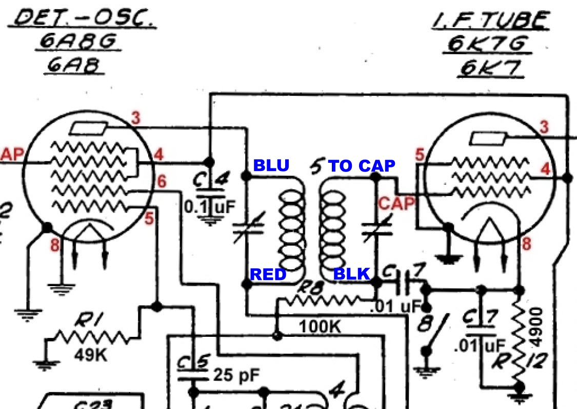
First, I needed to determine how the 1st IF transformer was hooked up under the chassis and determine wire colors. (I had erroneously called it the 2nd IF transformer in post #32 above which I have since corrected.)
I made this partial schematic to help me:
Next up: Getting the 6-S-254 chassis out of the garage and onto my workbench to remove its 1st IF transformer.
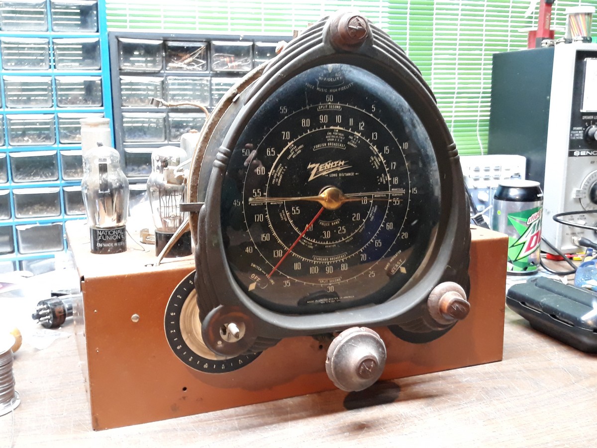
A look under its chassis:
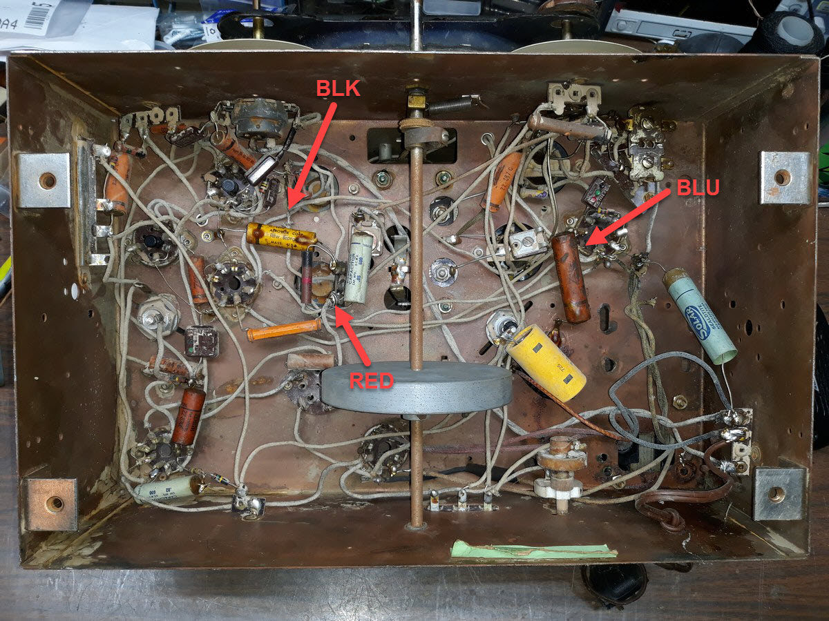
Finally, before I completely disconnected and removed the 1st IF transformer from the 6-S-128, I took this photo to remind myself how it hooked up under the chassis.
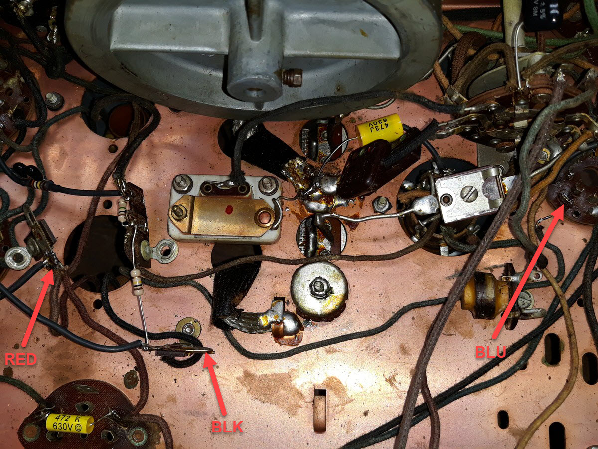
more...
--
Ron Ramirez
Ferdinand IN
Posts: 13,776
Threads: 580
Joined: Sep 2005
City: Ferdinand
State, Province, Country: Indiana
Now, a side by side comparison of the 1st IF transformer from the 6-S-128 and the 1st IF transformer from the 6-S-254.
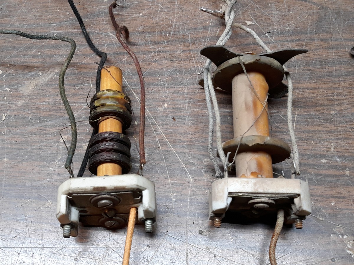
Hmmm. The windings are completely different. About all this told me is that (at least in the 1938 model), the two windings are spaced very far apart on the dowel.
So, just out of curiosity, I removed the shield can from the 6-S-128's 2nd IF transformer.
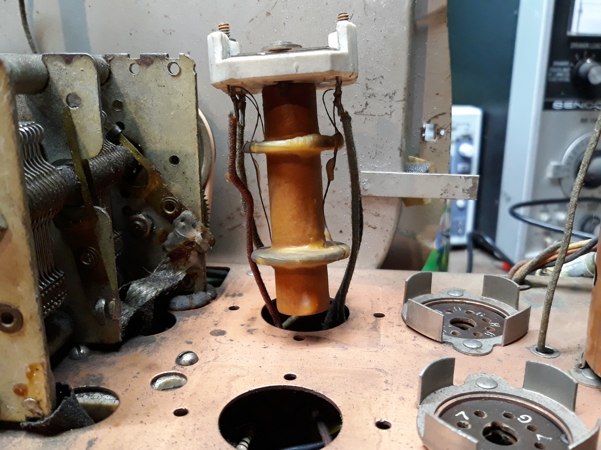
Hmmm (again). This one is made like the 1st IF from the 1938 Zenith.
Ultimately, I decided to attempt a repair of the 1937 model's 1st IF transformer.
I moved the lower winding almost to the bottom of the dowel (in a similar manner to the 1938 model's 1st IF) and then used hot glue on the bottom and top of the triple winding to hold them in place.
I had previously found the break in the lower winding and carefully pulled on it (fortunately, it was on the outside which made this possible). Luckily, the wire easily came loose, enabling me to remove a couple of turns. I then reconnected it to the proper terminal on the top ceramic insulator. I also installed new wires.
Here is the finished product:
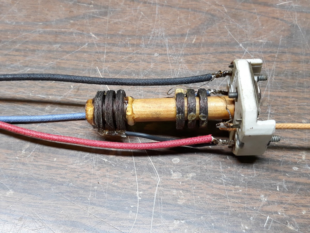
I checked continuity with my DMM. Primary 8 ohms, secondary 7.5 ohms. (It was a primary lead which was broken.)
Success! 
Now, two photos showing the original 1st IF can mounted back on the 6-S-128 chassis.
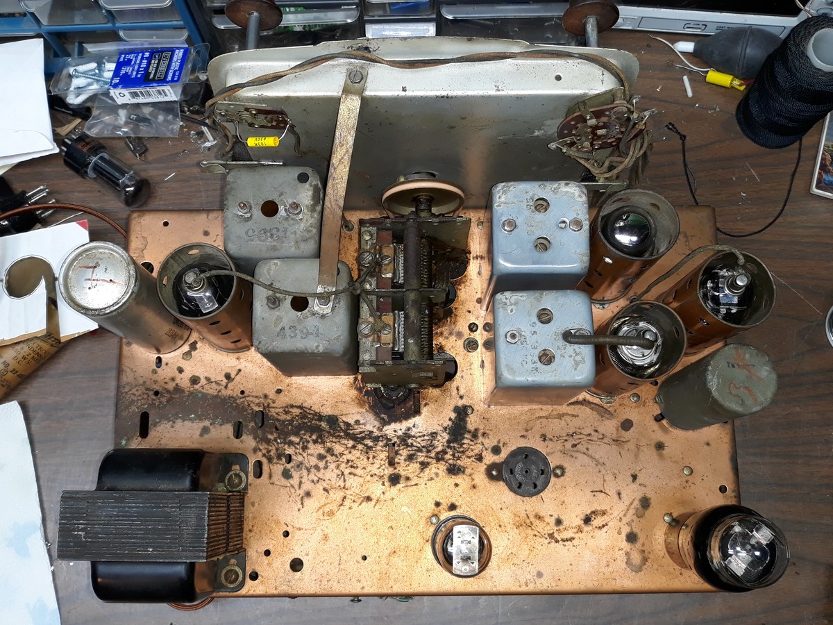
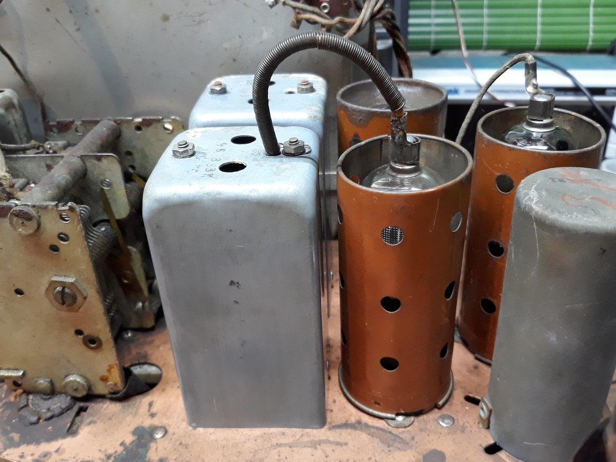
I failed to mention above that I had placed the mounting nuts and lockwashers in an Evapo-Rust bath and left them to soak all day, so the 1st IF, the 2nd IF shield can, and two nuts from one of the RF coils were not reinstalled until this evening.
I also checked continuity of the 2nd IF transformer. It sort of bothers me that its primary measures 69 ohms while the secondary is around 7.4 ohms. It makes me wonder if there is an issue with its primary? Well, I will find out when I try the set out for the first time.
I reinstalled the 1st IF from the 6-S-254 back onto its original chassis after replacing its wires. I did not hook it back up, though. The 6-S-254 chassis looks restorable and who knows, it may end up being restored as well. I don't know what I would do with it, however.
Anyway...
Other work accomplished today:
- Installed a new, cloth-covered AC cord and an old AC plug.
- Installed new LED dial lamps. (Now the burn marks on those light diffuser disks will never get worse!)
- Tested the chassis (with all tubes removed) by applying power. When the off-on switch was switched ON, the LED lamps lit up properly. No sizzling or other odd sounds were noted.
So after I test the tubes and make sure they are all OK, this chassis is now ready to try out. This will happen in the morning.
Until then... 
--
Ron Ramirez
Ferdinand IN
Posts: 5,005
Threads: 267
Joined: Nov 2012
City: Bandon
State, Province, Country: OR
Posts: 203
Threads: 5
Joined: Sep 2005
City: Newark, Ohio
 +1
Posts: 3,102
Threads: 54
Joined: Apr 2011
City: Lexington, KY
 +2
John KK4ZLF
Lexington, KY
"illegitimis non carborundum"
Posts: 13,776
Threads: 580
Joined: Sep 2005
City: Ferdinand
State, Province, Country: Indiana

Okay, here's an update.
8:00 am.
I tested all of the tubes. The 6A8G had an H-K short and was tossed. Luckily I had another, good 6A8G and it went into the 6-S-128.
I also replaced the 5Y3GT with a 5Y3G even though the 5Y3GT tested good. The 5Y3G is more "period correct" for this set.
I had decided last night that I should test the wave trap and the odd little coil (labeled "Antenna Choke" on the schematic). It is a good thing I did.
The wave trap was OK. But the antenna choke was open.
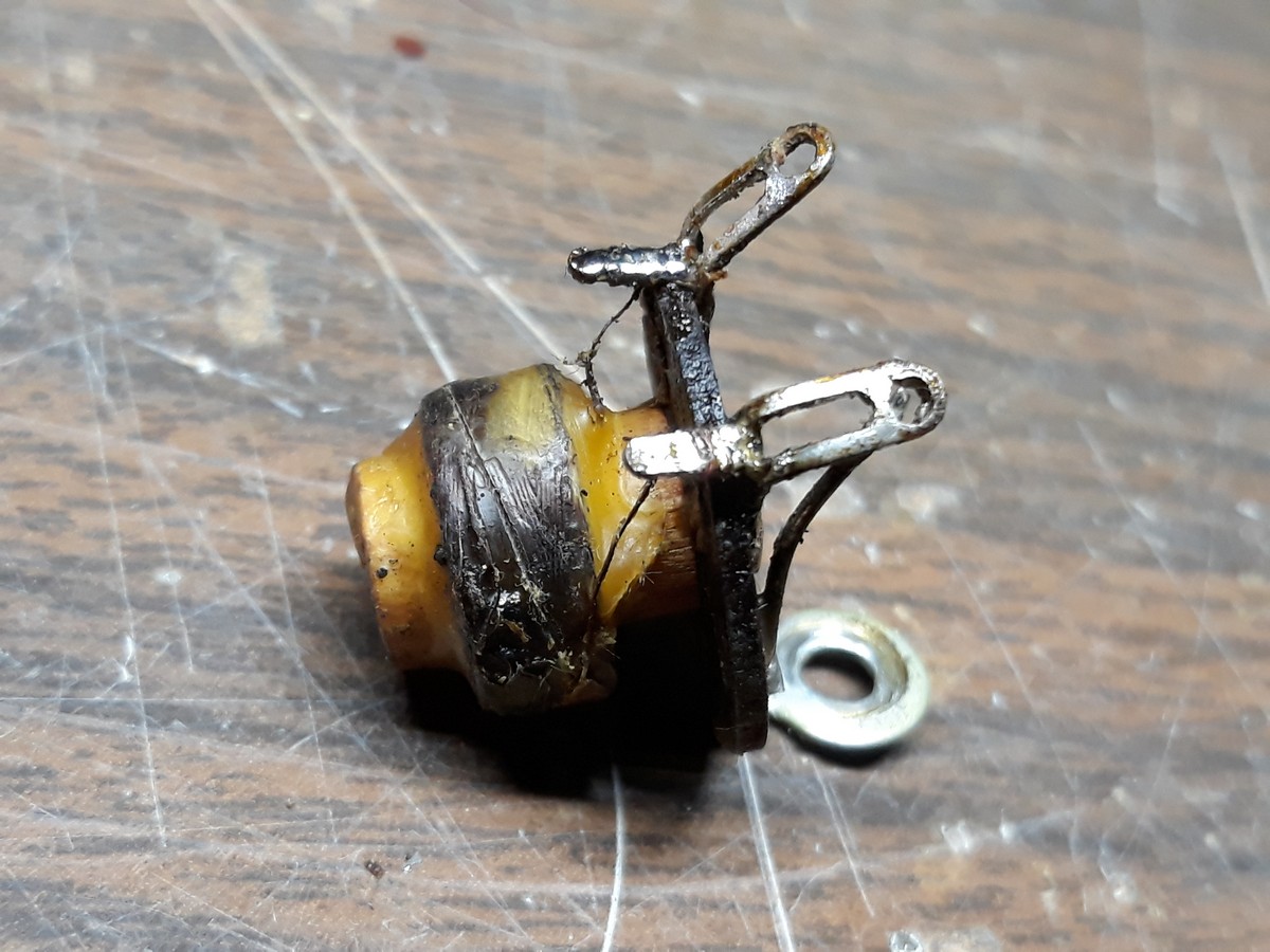
I thought I found a break at the beginning of the winding where it soldered to the terminal. I removed one turn and resoldered. Checked again, still open!  
Hmmm...what could I do to try out the radio until I either rewind or replace this antenna choke?
Philco to the rescue!
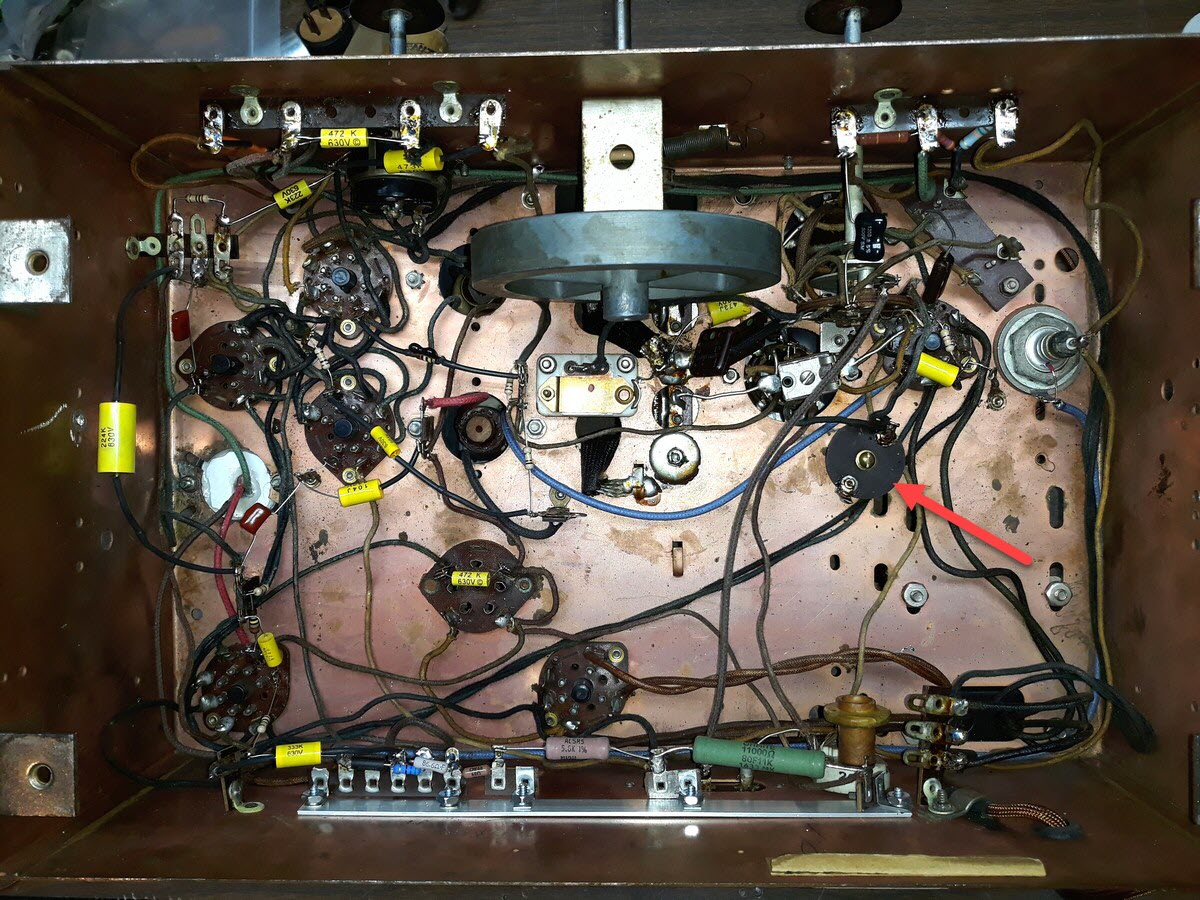
Then I remembered a little 2.5 mH RF choke that had been on my workbench since I converted my Philco 70 to AVC.
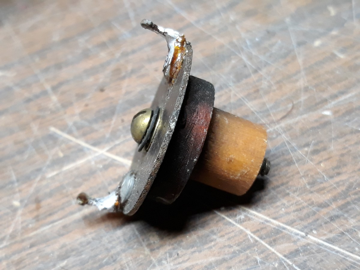
Yes, it measured 95 ohms on my DMM. 
So, in it went:
Finally, it was time. I removed the speaker from the cabinet, attached my longwire to the antenna terminal, and plugged the Zenith into my Variac.
I slowly brought up the voltage and...
NOTHING.
I touched the grid cap of the 6F5G and... NOTHING.
Then I noticed the screen grid of the 6F6G glowing bright red.
A tell-tale sign...bad audio output transformer!
I shut everything down, unplugged the speaker, and checked the field coil and the output transformer primary.
The field measured around 1800 ohms. I noted the schematic calls for 1000 ohms. I'm hoping that maybe I made a mistake and the field is OK.
Anyway...I measured output transformer primary, and... OPEN.
I couldn't help but say it out loud (only I said it in English)...
Черт побери!
A mild expletive. Google it if you're so inclined.
This radio has had one issue after another, and I'm tired of messing with it for now. Time to set it aside for awhile. The speaker is back in the cabinet, the 6-S-254 chassis is back in the garage, and the 6-S-128 chassis is still sitting on the bench.
--
Ron Ramirez
Ferdinand IN
Posts: 1,475
Threads: 69
Joined: Nov 2012
City: Kansas city, MO.
Yea sometimes you have to take a break from a problem chassis. It sounds like your are close sans the output transformer.
I have an 89 on the bench for a week now that could be a twin to yours. Meaning one problem after the next. 
Posts: 1,517
Threads: 240
Joined: Sep 2012
City: West Bend, Wisconsin
Ron,
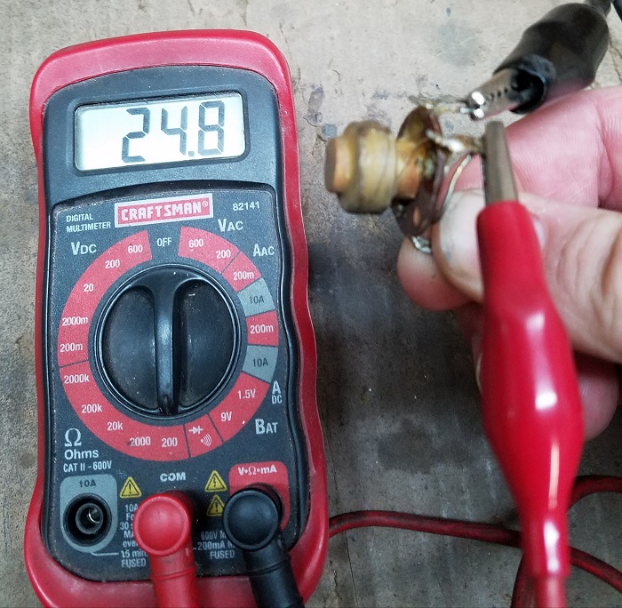
Sorry for the open coils you've been encountering. From my 6S152 parts chassis I have the antenna choke:
And the first IF transformer:
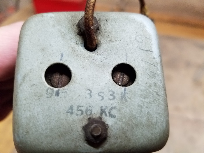
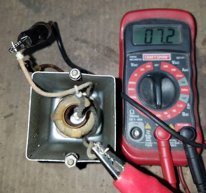
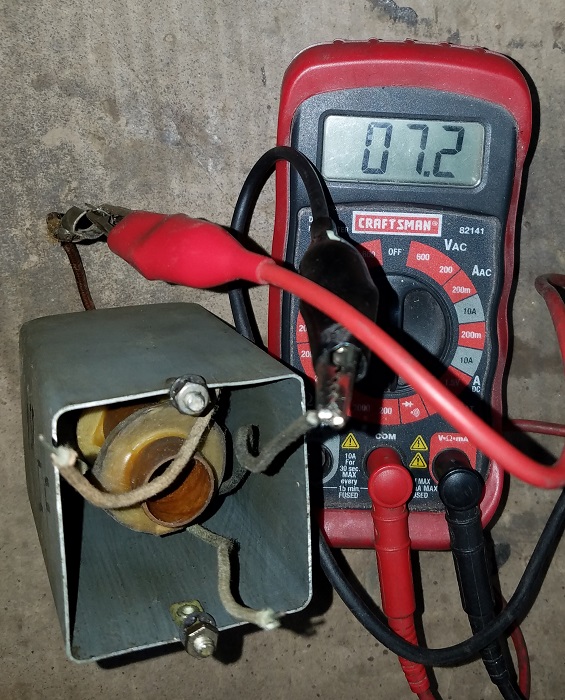
Now I didn't look on the schematic to see where the windings should be but I get 7.2 across the two beige colored wires, and across the black wire to the grid cap. Does that sound right? I get nothing from either beige wire to the black wire.
I've sent you a PM and will be happy to send these to you if you'd like.
Greg V.
West Bend, WI
Member WARCI.org
Posts: 1,517
Threads: 240
Joined: Sep 2012
City: West Bend, Wisconsin
Ron,
Here is what I get on the two windings of the 2nd IF:
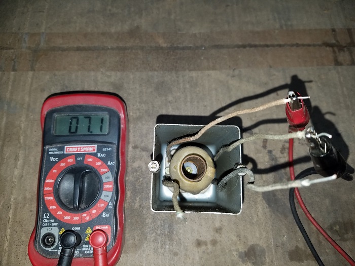
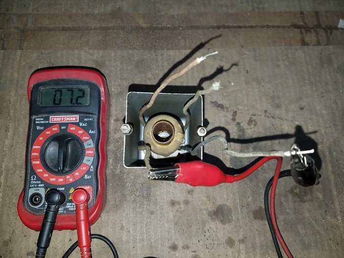
Greg V.
West Bend, WI
Member WARCI.org
Users browsing this thread: 1 Guest(s)
|


