Posts: 11
Threads: 3
Joined: Mar 2020
City: Leicester
State, Province, Country: North Carolina
Greetings all. First time on the forum and happy to have found it. I am in the middle of electrically restoring a 38-2. I've recapped the main chassis and rebuilt the four bakelite condenser blocks; they were way out of tolerance. I've also rebuilt the two electrolytics that were also way out of tolerance. I've rebuild and lubricated the dial mechanism also as it was frozen, had to make a new flex coupling. I have some more resistors on the way, I found a couple that had scorch marks and cracks.
I can not figure out how to access the center tuning section, there are two more bakelite blocks in there that I'm pretty sure will be out of tol. also and i'd like to clean it up and lubricate where appropriate.
Can anybody steer me in the right direction on access to the center sub-chassis (I think it holds the tuner section)?
Cheers, Link
Posts: 7,215
Threads: 266
Joined: Dec 2009
City: Roslyn Pa
Hi Link and welcome,
I don't know that there is a step by step instruction for removing the center section of the chassis. The general instructions is to take lots of pic of how wires are connected and how mechanical things are fitted together. Mark all wires coming out of the sub chassis and where they connect to. Unbolt and unsolder as necessary till you get it apart. Replace rubber washers and reassemble.
I think most of us just start at it and keep going till it's done. Do go slow and be careful not to damage parts. Keep the tuning cap closed while working to lessen the chance of damage. While you have it apart check for open coils it happens sometimes.
When my pals were reading comic books
I was down in the basement in my dad's
workshop. Perusing his Sam's Photofoacts
Vol 1-50 admiring the old set and trying to
figure out what all those squiggly meant.
Circa 1966
Now I think I've got!
Terry
(This post was last modified: 03-24-2020, 06:23 PM by Radioroslyn.)
Posts: 11
Threads: 3
Joined: Mar 2020
City: Leicester
State, Province, Country: North Carolina
Thanks Terry, sounds like great methodology. I'd like to start by just getting the cover off to take a look, that's the part holding me up. If I can't get beyond the cover, it's no use cutting and marking wires.
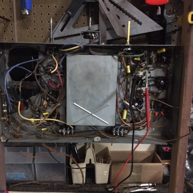
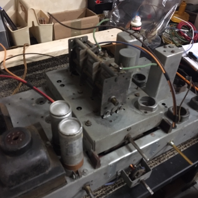
I may not have explained adequately, I've attached a top and bottom pic of the chassis. It is floating between the two front supports in rubber and one bracket on the back. When I removed the aft bracket, the tuner was free to mover about 3/8ths of an inch, but not enough to move it up or down.
There are three nuts located on top, along with some trimmers, but they don't appear to be structural, more like holding a component inside. Not sure I want to try them. I'm a bit stumped!
Posts: 7,215
Threads: 266
Joined: Dec 2009
City: Roslyn Pa
To be honest I stay away from the '37/'38 models and am not too crazy about the '39 thru '42 models unless they are something special. Do have a couple of 37-116's and a 41-300. Truth be told the older sets the w/cloth covered/rubber wire is starting to dainty...
When my pals were reading comic books
I was down in the basement in my dad's
workshop. Perusing his Sam's Photofoacts
Vol 1-50 admiring the old set and trying to
figure out what all those squiggly meant.
Circa 1966
Now I think I've got!
Terry
Posts: 1,181
Threads: 48
Joined: Oct 2017
City: Allendale, MI
I must be a little weird! I kind of like working on the RF chassis of the 37 and 38-116's (the only ones of this style I've worked on). A bit of a challenge to be sure, but I like things that are a bit complicated. Be sure to check the coils carefully. You probably don't want to take one of these apart more than once.
Posts: 108
Threads: 23
Joined: Oct 2016
City: Whitehall PA
Hello,
There are 4 nuts on top of the RF chassis that hold the bottom cover on. Remove them and off it comes.
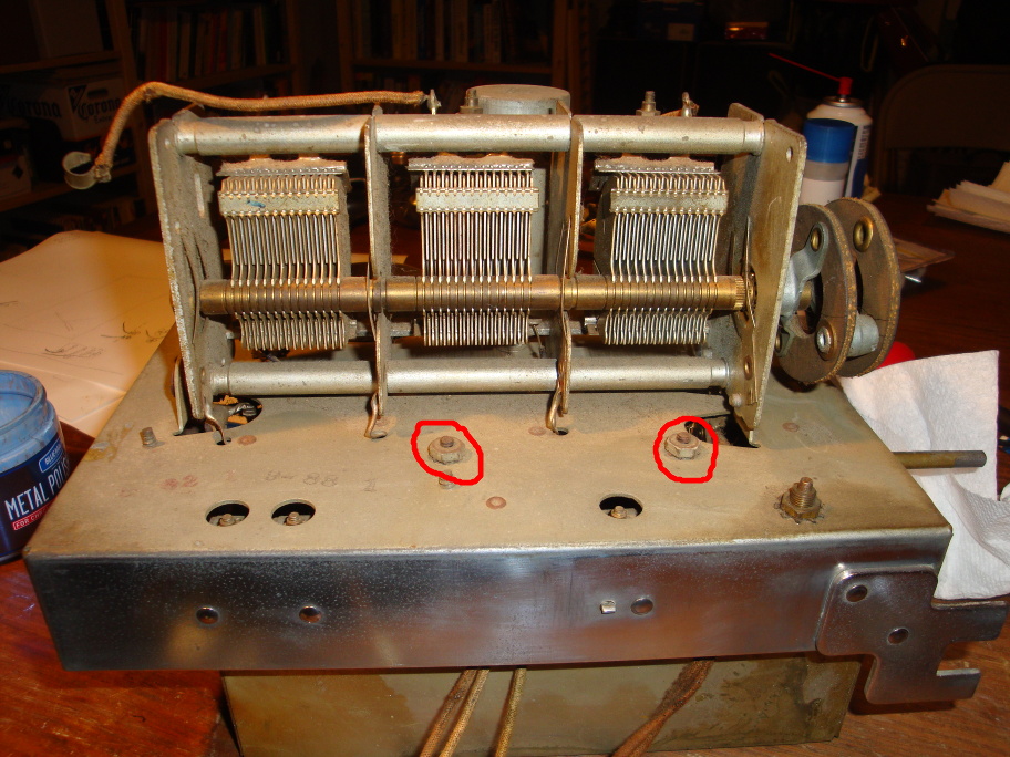
The cover looks like this:
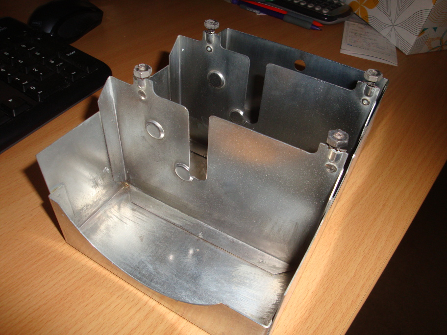
This is what's underneath, or should I say above:
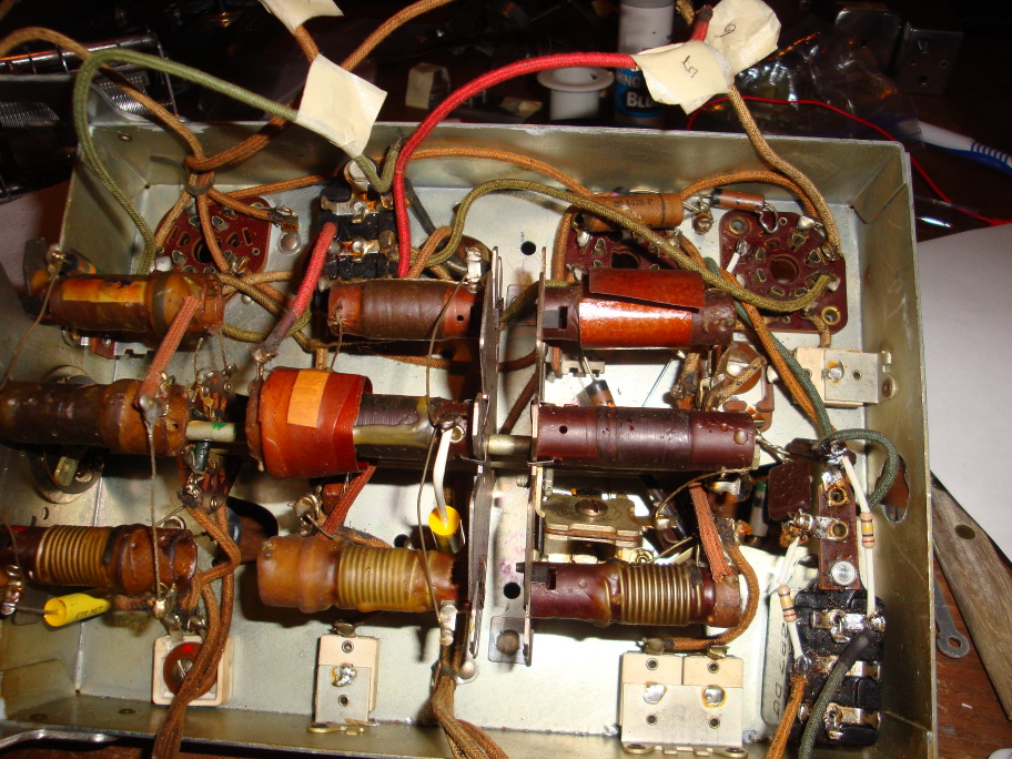
I usually label the wires and draw a picture showing their destinations and their assigned number. I think there are 16 wires that connect the RF chassis to the rest of the radio. I would also recommend taking photos if you can.
Good luck.
Can't think of anything witty.
Greg O.
Whitehall, PA
Posts: 11
Threads: 3
Joined: Mar 2020
City: Leicester
State, Province, Country: North Carolina
You're a lifesaver Greg! Wahoo!!! I'm back in the game!
Cheers man!
Posts: 11
Threads: 3
Joined: Mar 2020
City: Leicester
State, Province, Country: North Carolina
Hi folks, this is not an electrical question. All the energy put into being careful with the dial parts and I went and bumped it with my elbow and broke the Dial mask.
Anybody out that know of a source for one or a good technique to repair without impacting the illumination to much?
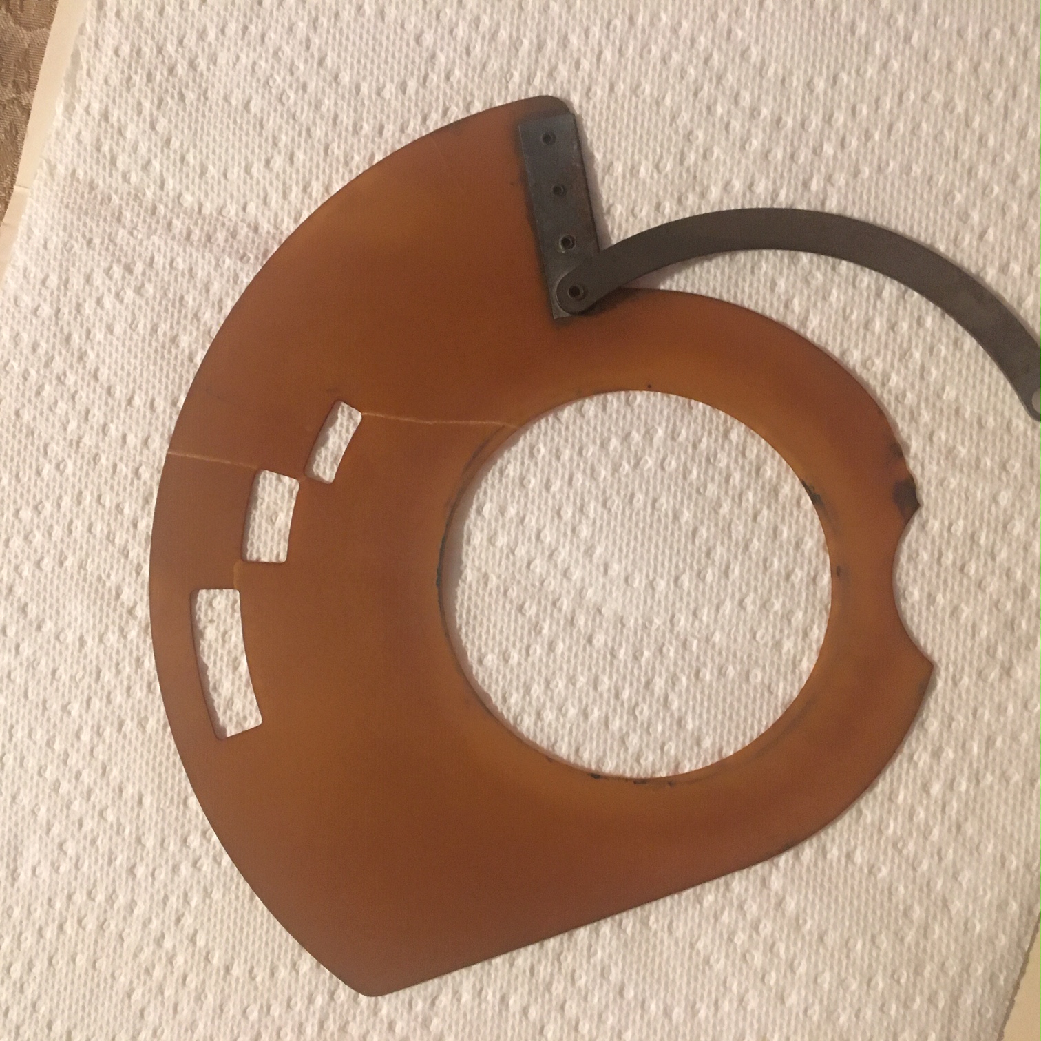
It took a while to come down off the ledge...….
Posts: 7,215
Threads: 266
Joined: Dec 2009
City: Roslyn Pa
I've used clear packing tape on the back side to hold it together.
When my pals were reading comic books
I was down in the basement in my dad's
workshop. Perusing his Sam's Photofoacts
Vol 1-50 admiring the old set and trying to
figure out what all those squiggly meant.
Circa 1966
Now I think I've got!
Terry
Posts: 4,336
Threads: 407
Joined: Jun 2011
City: Boston
State, Province, Country: Massachusetts
There are clear epoxy products on the market, I have not used them no experience. I have primarily used epoxy on bakelite cabinets on the inside to secure cracks or do a repair with good results. I usually put it on thick and even with the clear that may not look good when dial is lit.
You could always do a few tests on similar materials and see what you think before you do on the dial. Good luck. 
Paul
Tubetalk1
Posts: 11
Threads: 3
Joined: Mar 2020
City: Leicester
State, Province, Country: North Carolina
Well, my 38-2 is all back together, came back to life. I brought power to the chassis in stages; without tubes, with tube but no rectifier, than all tubes. All I could get out of it was a very low hum. I've rebuilt all the electrolytics. My plan is to disable the audio shorting mechanism in the dial assembly, pretty simple and I did have to work on it for a bit as it was in pretty rough shape, and kept shorting out. I thought I had it working well prior to reassembling it, it is the only thing I can think of as it has a full set of new tubes as well, all tested good.
Any ideas out there that I'm not thinking of?
Thanks, Link
Posts: 11
Threads: 3
Joined: Mar 2020
City: Leicester
State, Province, Country: North Carolina
Success! I want to thank the folks who had suggestions for fixing the Dial mask. I ended up doing a combination of them and got it back together nearly flat. It was warped before so it is actually turning in the chassis much better.
After much troubleshooting I found an open 7.5K wire-wound resistor mounted on the sidewall that was open. Fastened one in parallel to it and the radio came to life, good AM reception, sporadic reception across the other bands.
The audio is real weak unless I hover my hand hear the tuning capacitor. If I hover my hand over it, the volume goes way up, I'm guessing this is a reception issue or a shielding issue. If I place my index finger on the wire connected to the top of the 6S7G that is connected to the top of the tuning capacitor, the signal clears right up, crystal clear.
Is there more than one issue here? Low power, shielding or am I acting like a great big antenna when my hand gets close to the tuner?
I've got all the lights off in the garage thinking it might be the fluorescents, the only other item is the main circuit breaker panel is only about 4 feet away from my workbench though I don't hear any 60Hz hum overriding anything.
Thoughts?
Cheers, Link
Posts: 108
Threads: 23
Joined: Oct 2016
City: Whitehall PA
Hi,
I'm guessing the 6S7 was substituted for the 6U7 RF tube.
Sounds like you are the antenna. Do you have an antenna connected? if not, several feet of wire should be OK for now.
If you do have an antenna attached I would check to see if there's a break in the path between the antenna and the grid of the 6S7. By touching the grid you are bypassing the antenna and filter in front of the tube. Does this affect only one or all of the bands?
Look here for schematics if you don't have one. They seem to have clear copies:
https://www.tubesandmore.com/schematics/...-corp/38-2
Specifically:
https://www.tubesandmore.com/sites/defau..._pg8-1.png
The path from the antenna to the 6U5 grid starts at terminal "A" (antenna terminal at top left of schematic) through C1 (band switch) through the selected transformer (1-BC,2-SW1 or 3-SW2) through C12 and to the grid of the 6U7. If something in that path is broken the there's essentially no antenna and no, or very little, signal to the tube. I'm guessing something may be bad in this path for the affected band(s).
Greg
Can't think of anything witty.
Greg O.
Whitehall, PA
Posts: 11
Threads: 3
Joined: Mar 2020
City: Leicester
State, Province, Country: North Carolina
Thanks Greg, I did have a wire connected. I will run through that check you suggested, makes perfect sense, did not consider that possibility.
Cheers, Link
Users browsing this thread: 1 Guest(s)
|


