05-31-2020, 03:06 PM
Gentlemen.
I have just gone through this receiver, 1936 model, and just for the record, I took pictures of every conceivable angle before I replaced any components. I restuffed the original bypass and coupling capacitors, swapped nearly all the resistors(only the ones that were bad by 20% or more) and replaced all the 'lytics.
This problem did not show up on the original dogbone (2K part # 80 on the schematic, it showed no signs of overheating. The only part that showed signs of overheating was the .3 uf capacitor that goes across the filter choke (101). Of course, this was swapped out. The only difference is that the schematic showed one .3 uf cap, while there was two .3 uf caps in the bakelite cover. I put two back in it. Production change?
When I first energized the chassis after rebuild, I did it slowly on a variac, and only did I noticed at around 90-100 V, that the resistor was slightly discolored and I could smell something cooking. I use 1 W flameproof resistors throughout the rebuild. I actually burnt several of these up trying to locate the cause of the problem.
Of course, I double check all my connections and work, comparing with the before pictures and no components are out of place. No shorts, no backward components.
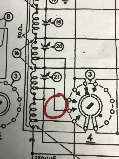
I started back tracking by disconnecting all the wiring associated with the 2K resistor and shadowmeter. Starting on the B+ side and working my way back until I came to where the wires attach the longwave RF transformer. Both of the these go to the bandswitch wafer marked as #4 on the schematic. As you are looking at the chassis with the controls facing up, its the bottom two wires on the transformer that go to the bandswitch.
Jumping either one of the wires from the bandswitch back to the longwave transformer, results in cooking the shunt resistor. Another thing that I observed is as long as the bandswitch is in upper band (SW) there is no problems, so as you select the lower bands, the trouble starts.
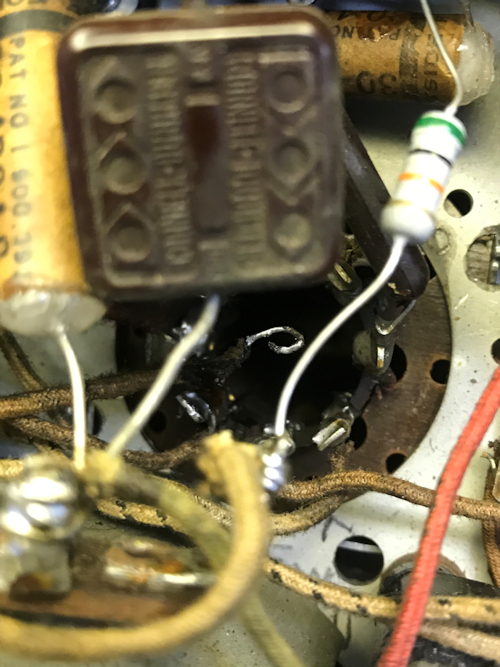
I cleaned the bandswitch with Deoxit, thinking that maybe I had a carbon track causing the shorting issue, but that made no difference. While poking around the area I found a broken wire that goes from the bandswitch to the RF transformer (BC, SW and Police bands). It is quite confusing to know which terminal this would attach to and wondering if it may be the cause of the problem. I circled the wire on the attached schematic. I have also attached a pic showing the detached wire.
Something is making this shunt resistor draw excessive current and I can't quite put my finger on it. I'm usually pretty good figuring these out, since I do have an electrical background. But I'm just about ready to put the radio in the "land of misfit radios" (upstairs above my little hobby shop)
Thanks in advance for any help, tips, suggestions.
Jack of all trades, master of none. I know just enough to be dangerous


