Posts: 348
Threads: 48
Joined: Oct 2013
City: Tioga, Texas, USA
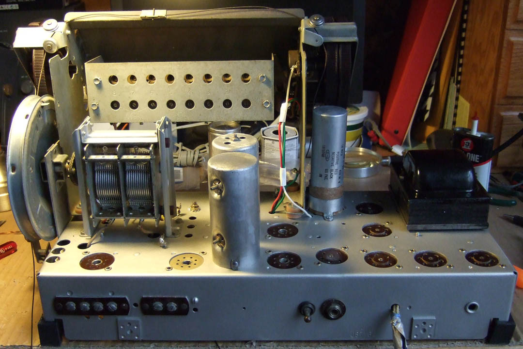
Last night I spent time reinstalling the electrolytic capacitors. They are not connected yet. I am going to have to add some terminal strips to use them as they are restuffed and have flying leads. I rewired the push-button switch assembly. I am using some left over wire from some discarded electronic equipment to repair the Philco. There are two leads that will come from the bank of coils and push-button switches. One now has a yellow insulated wire to go under the chassis and the other is a black wire. I have to determine where to connect them as the mice had completely chewed them away.
I discovered there are some more rubber grommets on the tuning control assembly right up at the dial area that are crumbling too. I will have to measure them and find replacements.
I used some white acrylic paint and the smallest artists brush I have to paint a white stripe on the band-switch knob because the original paint had long since disappeared. Now it will be easy at a glance to see what position it is in.
Somehow, I managed to loose one of the 1/4" machine screws with captive starwasher that holds the tuning capacitor mounting brackets together. I had them until I took the brackets apart for painting yesterday. It is still here somewhere. I just need to clean off the desk top and find it (or look through my collection of old hardware in the barn). I am basically a pack rat and never throw things away.
Thanks to all of you who have made suggestions and provided encouragement!
Joe
Posts: 348
Threads: 48
Joined: Oct 2013
City: Tioga, Texas, USA
Regarding the black wire coming from the push-button switches: this wire is to serve as a ground for the coils and trimmer capacitors. The question I have is, does it matter exactly what ground lug I solder it to on top of the chassis? I am pretty sure it goes topside and not underneath, because I never saw a black cotton covered wire under the chassis coming to any of the holes in the chassis in that area. There are two ground lugs on the chassis that the control panel itself grounds to. I have two short green wires being used for that purpose. The tuning capacitor assembly gets grounded to two ground lugs closer to the tuning capacitor I believe. It may not make much difference on AM, but might possibly make a difference on SW.
On the pictures I took before taking anything off the chassis, but minus the tubes and control assembly, I can see one light colored (yellow or white?) cloth covered wire that descends through a hole just in front of the tuning capacitor. I believe this is the signal lead coming from the station preset switches that goes to a switch lug on the bandswitch closest to the side of the chassis. Underneath the chassis this wire appears orange or brown, maybe a discolored red? The lug this wire is connected to is near the chassis top metal viewed from underneath the chassis.
Can someone with a 40-195, 40-200 or 40-201 look at their chassis and see where the black cloth covered wire from the station preset switches is grounded? Also where the cloth covered lighter wire I mentioned above connects to? The black wire may not be visible without a mirror and a flashlight if the chassis is in the cabinet. The lighter colored wire would not be visible without having the chassis out of the cabinet. That wire connects to either capacitor number 24 (a 370pfd) or capacitor number 23 (a 270pfd). It looks like there needs to be another wire from one of these capacitors to a different bandswitch lug. I need to do some more checking.
Thanks in advance.
Joe
(This post was last modified: 11-30-2013, 10:37 AM by
Joeztech.)
Posts: 348
Threads: 48
Joined: Oct 2013
City: Tioga, Texas, USA
I was right! The yellow wire I connected attaches to one end of C23. There is part of a darker colored cloth covered wire the mice chewed into that is connected to a bus wire that passes through all the trimmer capacitors on the push-button switch circuitry. I think this is the wire that connects to C24 and also is supposed to go to the bandswitch. Right now I do not see the remains of it under the chassis though. The wire from C23 should go to terminal B3 and the wire from C24 should go to B12 if I am reading the schematic correctly.
Joe
Posts: 348
Threads: 48
Joined: Oct 2013
City: Tioga, Texas, USA
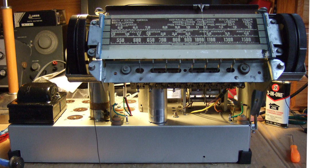
Today I managed to get the chassis reassembled. All the major parts are on the chassis now and the control panel wires have been reattached to the band switch and the audio controls. I retained the OEM cloth covered wires from the coils below up to the tuning capacitor lugs.


I had to study the schematic closely to determine exactly which wire from C23 and C24 went to which lug on the band switch. One wire from the push-button trimmers goes to the band switch A-8. I used an orange wire for that as it matched the original color as best I could determine. The lug it attaches to on the band switch is close to the chassis and very difficult to get to, so I trimmed the remaining cloth covered wire back some, soldered the new wire to it under the chassis and insulated it with some heat shrink tubing and black electrical tape. The lead from C23 attaches to band switch B-3. I used a yellow wire for that. The lead from C24 attaches to band switch B-12. I used a violet wire for that.
I replaced the audio wires with black, green and red going to the volume control and a white wire going to the tone control. These wires went all the way to terminal strip lugs underneath the chassis.
A lot still remains to be done, but the rest will be easier for me as it is just some more wiring and trouble-shooting. The IF transformers have new color coded wires attached and still have to be reconnected to the tube sockets and other points. The electrolytic capacitors are mounted, but still have to be wired into the circuit.
Joe
Posts: 348
Threads: 48
Joined: Oct 2013
City: Tioga, Texas, USA
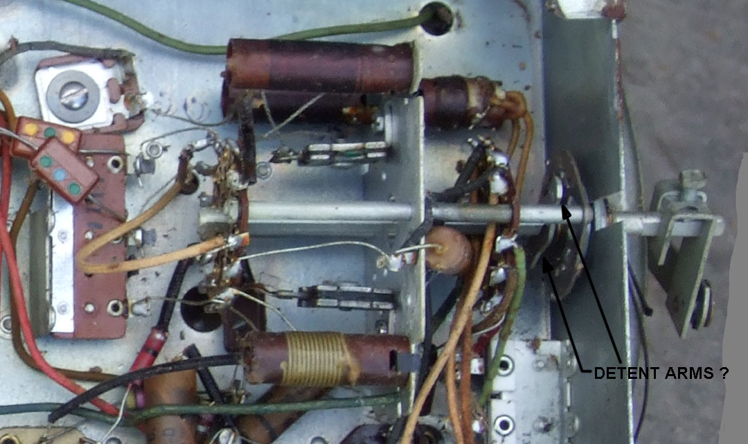
One thing I noticed in the action of the band switch - there does not seem to be a good positive detent to its action. It just slides through each position. There is a very slight feel of resistance as a band position is reached, but this just seems not right. I seem to remember seeing most band switches having a spring loaded ball bearing that provided a nice positive position feel. This band switch does not have any spring detent mechanism to it. There are two arms that are attached to the shaft and there are raised metal bumps on the front flange of the assembly but nothing is there to provide a positive detent. Is this normal, or has something broken and fallen out of the band switch?

Joe
(This post was last modified: 12-01-2013, 05:49 PM by
Joeztech.)


