02-16-2014, 01:10 PM
Since my model 89 has the K-21 speaker, but still has the #36 tube, I've determined my set is somewhere between schematics #6, #7, and #8 in the http://www.philcoradio.com/tech/89evol.htm section. My question concerns the change made between November 15, 1933: Code 123, Run 7 and December 1, 1933: Code 123, Run 9 :
"Condenser 3615-L, .05 uF, formerly in parallel with .09 uF section of condenser ( 8 ), removed. Condenser (5), 4989-AG (.09 uF with 300 ohm resistor) removed. Above three parts replaced by condenser 4989-H (twin .09 uF) and flexible resistor 33-3010 (300 ohms) added from cathode of RF socket and ground."
My # 44 RF tube has what looks like a little cloth covered worm between the cathode to ground. I'm assuming that is the flexible resistor 33-3010 (300 ohms) mentioned above? Mine reads open so I can't verify the value.
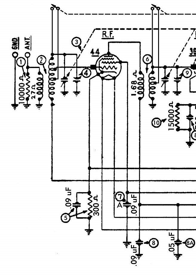
Code 123, Run 7 looks like this:

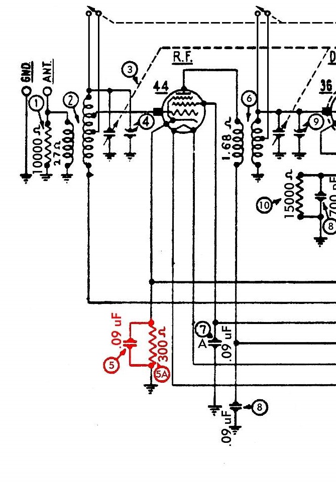
And Code 123, Run 9 looks like this:

For the bakelite block shown as #5 in Run 7, and as 5 and 5a in Run 9, if I'm reading that right, having that little cloth covered flexible resistor replaces having a 300 ohm resistor and the .09 mfd capacitor inside the bakelite block? In other words, should there just be a .09 mfd cap in the block, and that separate 300 ohm resistor outside the block, mounted from the cathode of the #44 tube to ground?
My theory for this is the separate designation on the bakelite block on Run 7 of the . 09 mfd cap & 300 ohm resistor as being just #5, and on Run 9 it became #5 for the cap, and #5a for the resistor.
Any thoughts, ideas, whacks along side the head would be most helpful
"Condenser 3615-L, .05 uF, formerly in parallel with .09 uF section of condenser ( 8 ), removed. Condenser (5), 4989-AG (.09 uF with 300 ohm resistor) removed. Above three parts replaced by condenser 4989-H (twin .09 uF) and flexible resistor 33-3010 (300 ohms) added from cathode of RF socket and ground."
My # 44 RF tube has what looks like a little cloth covered worm between the cathode to ground. I'm assuming that is the flexible resistor 33-3010 (300 ohms) mentioned above? Mine reads open so I can't verify the value.
Code 123, Run 7 looks like this:
And Code 123, Run 9 looks like this:
For the bakelite block shown as #5 in Run 7, and as 5 and 5a in Run 9, if I'm reading that right, having that little cloth covered flexible resistor replaces having a 300 ohm resistor and the .09 mfd capacitor inside the bakelite block? In other words, should there just be a .09 mfd cap in the block, and that separate 300 ohm resistor outside the block, mounted from the cathode of the #44 tube to ground?
My theory for this is the separate designation on the bakelite block on Run 7 of the . 09 mfd cap & 300 ohm resistor as being just #5, and on Run 9 it became #5 for the cap, and #5a for the resistor.
Any thoughts, ideas, whacks along side the head would be most helpful
Greg V.
West Bend, WI
Member WARCI.org


