03-21-2014, 09:08 AM
I have traced down the diagram and found the under chassis location number of the caps in the diagram is wrong. The schematic is correct. Looking at the chassis from the top rear (dial to the front), the right rear cap is the input cap off the rectifier tube #56 8mf, and is the insulated ground, the cap to the left of that, nearest the 80, is the output cap, #54 8mf, the cap in the middle closest to the power transformer, with all the resistors under it is the #41, 16mf cap. I used a 10mf 450v cap for the 8's.
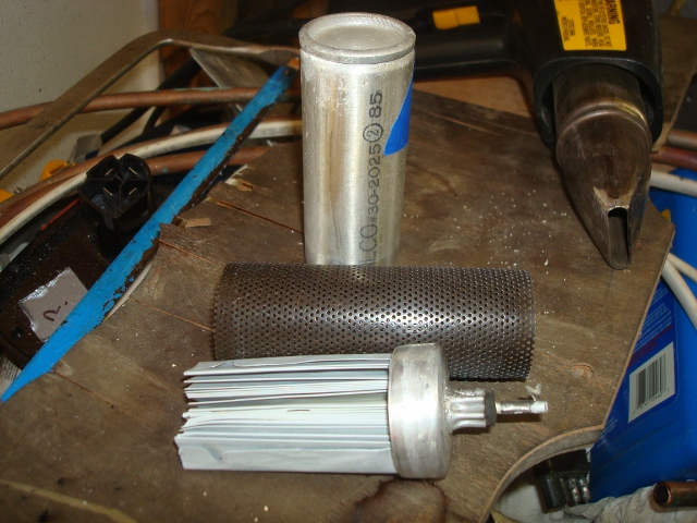
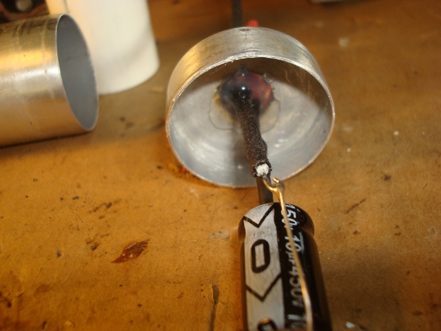
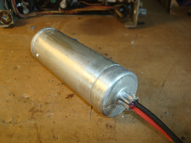
Here are some shots of the wet can rebuild:


I used a tubing cutter on this one, but it was a little tricky. It kept wanting to track off. The next one, didnt go good at all with the tubing cutter, so I quit and used a hack saw to finish. Not real proud of it, but it will be hidden in the clamp. I found it useful to mark the cans with a marker to help the line up when done. I didnt pot the caps, but did seal them through the hole where I ran the wires go through with hot glue. Holds things in place real nice. I used shrink wrap over the + wire of the cap. I didnt glue the can together and left enough wire inside to make re-replacement easier for the next time around. The clamp seems to hold things in place. Ill post a shot when I have them in place and tested.
Here are some shots of the wet can rebuild:
I used a tubing cutter on this one, but it was a little tricky. It kept wanting to track off. The next one, didnt go good at all with the tubing cutter, so I quit and used a hack saw to finish. Not real proud of it, but it will be hidden in the clamp. I found it useful to mark the cans with a marker to help the line up when done. I didnt pot the caps, but did seal them through the hole where I ran the wires go through with hot glue. Holds things in place real nice. I used shrink wrap over the + wire of the cap. I didnt glue the can together and left enough wire inside to make re-replacement easier for the next time around. The clamp seems to hold things in place. Ill post a shot when I have them in place and tested.
If I could find the place called "Somewhere", I could find "Anything"
Tim
Jesus cried out and said, "Whoever believes in me , believes not in me but in him who sent me" John 12:44


