RCA 110K2 Unexpected project
Posts: 1,275
Threads: 44
Joined: Nov 2017
City: Menlo Park
State, Province, Country: CA
I probably paid too much, but the replacement knobs came in, and they look nice after a gentle polishing. Brasso works wonders on Bakelite  . I might choose to detail the gold paint inlay on these.
The work choice comes down to getting the cabinet sorted, and the harder work out of the way first or going straight for the electronics. I'll probably do a bit of both.
I don't hold with furniture that talks.
Posts: 1,275
Threads: 44
Joined: Nov 2017
City: Menlo Park
State, Province, Country: CA
I started the notebook on this one today. Details of bandswitch wiring etc. etc. Also checked all windings on the power transformer which test fine with the ohm meter. Then on to testing a few resistors - quite a few of which seem to be 50's or 60s replacement "Allen Bradley" style composition types, and they have gone high/bad.
As to wiring, the stranded stuff seems all to be cloth over rubber, and the solid core is rubber covered. The rubber is hard and cracking up in many places, but at least has retained it's colour. The cloth stuff, after 70+ years bears no resemblence to the shades called out on the service info, and has frayed badly.
Onto a little work. The set has a large loop antenna, and I decided at least to replace the wires that lead to it - a delivery of cloth covered wire arrived this week. This was a test case, as these two wires were attached to the bandswitch in a very tricky location. With a little fiddling, the job was done.
More note taking and checking to come. I do need to order some resistors as well.
Cheers
Ed
I don't hold with furniture that talks.
Posts: 1,275
Threads: 44
Joined: Nov 2017
City: Menlo Park
State, Province, Country: CA
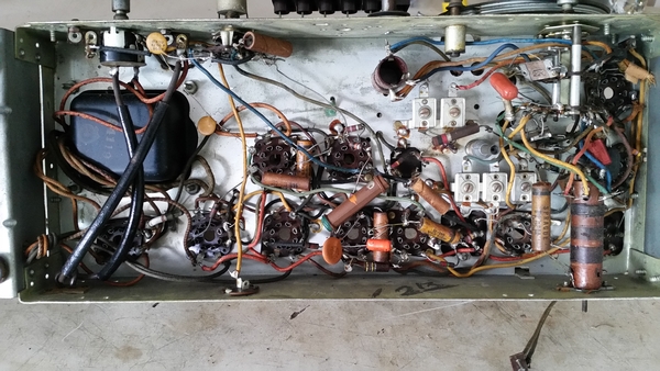
Here's a pic or two of the underside:

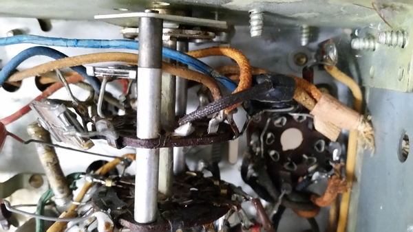
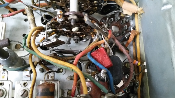
And here is the tangle around the bandswitch.


I don't hold with furniture that talks.
Posts: 1,275
Threads: 44
Joined: Nov 2017
City: Menlo Park
State, Province, Country: CA
A nice resistor kit just came in - Needed one of these anyway!
I also needed, and ordered 20 gauge hookup wire in a kit of colours. I suppose one has to use PVC insulated stuff these days? I plan to use cloth covered wire where it was used originally, but the PVC to replace the rubber covered stuff. It is a shame to lose original materials, but it is very crumbly. Since this isn't a pristine original radio, it seems to be an easier choice to replace with more modern (and reliable) materials, especially as the goal is to ensure it is safe to operate.
I don't hold with furniture that talks.
Posts: 4,611
Threads: 51
Joined: Sep 2008
City: Sandwick, BC, CA
Russ likes to use EPDM covered wire as a substitute for the old fashioned rubber/gutta percha wire in many of his restorations, so that is an option if you want to avoid the vinyl wire look, which matters more in something like an A.K cathedral. In a common set from the 1940s it doesn't really matter, after the war most manufacturers switched to vinyl insulated wire anyhow, just do a neat job and nobody will look twice. I would get rid of the disk caps someone used though, even they yellow poly film ones look better in a pre war radio, but then again they may have used the wrong value ones anyhow in a quick and cheap "restoration" job.
Regards
Arran
Posts: 1,275
Threads: 44
Joined: Nov 2017
City: Menlo Park
State, Province, Country: CA
Thanks Arran,
I'll look up pricing on the EPDM wire, but in a way it is no more original than PVC, and as you say - who will ever look or know except me, or perhaps the next restorer in 50 years!
I agree with you on changing the dodgy discs, and will be checking values carefully. Also I need to figure out a solution to the 4 section electrolytic - might restuff it. For a radio that makes a big show of things up front, the chassis and circuitry is fairly basic. It will be interesting to see how it performs.
Regards,
Ed
I don't hold with furniture that talks.
(This post was last modified: 04-05-2018, 11:32 AM by EdHolland.)
Posts: 1,275
Threads: 44
Joined: Nov 2017
City: Menlo Park
State, Province, Country: CA
I spent a little time with this radio today. First off was to try and see what would remove the yellow deposit from the chassis metalwork. Rubbing gently with paint thinner (the eco friendly stuff that seems useless for brush cleaning) works a charm. That led me to the odd splashes of green paint or whatever it is on the chassis in one area. Odd, but they lifted with gentle working away with a thinner soaked rag. The blanket film of yellow gunk is probably tobacco smoke residue.
The screws securing the power transformer were removed, and the top cover given a light sand and coat of black paint. Whilst it was loose, I could also give the chassis in that area a thorough clean.
Then I saw that the wire on one of the preset RF coils was starting to unwind, so spent a little time securing it, at which point I noticed that the six wires completing the tuning circuits were rubber insulated in green... Sure enough, on close inspection, this insulation had melted at some point - the wires being directly above two of the valves on the chassis.
All in the name of progress, and observing what needs attention.
I don't hold with furniture that talks.
Posts: 4,611
Threads: 51
Joined: Sep 2008
City: Sandwick, BC, CA
I think that the EPDM covered wire costs more then the vinyl covered stuff, I haven't bothered to search for it since I have several 100 foot rolls of 18 gauge stranded to handle most of the rewiring jobs such as replacing speaker or eye tube cables. The wires on the pushbutton assembly are probably something like 20 gauge solid core wire, if the insulation is melting off that isn't very attractive, but the assembly isn't really carrying any voltage, so as long as nothing is shorting out you can ignore the bare wires, if you want to replace them, or sleeve them, do it one wire at a time so you don't get any of the dozen wires mixed up.
With regard to the filter condenser can, you can restuff the original, and there are several different methods for getting them apart and removing and replacing the contents, or you can install a terminal strip in it's place under the chassis, or if you are very lucky find alternative places to install the individual caps. The latter will often not work since in sets with a field coil speaker they often have the two field coil wires from the speaker cable routed directly to the terminals under the condenser can, so you are still stuck with either splicing onto the original wires or adding a terminal (tag) strip. One that you easily could leave out of the filter can is the cathode bypass cap used on the power output tubes, if this set has one, that goes straight from the cathodes to ground, in this case the chassis, then you only need to work out what to do with the three filter caps.
Some guys can cut open a condenser can and restuff it without even removing it from the chassis, I guess if you have a pipe cutter that will fit around it you can do this, or you could wrap tape around the can to act as a straight edge and use a Dremmel tool cutting wheel, or a jeweler's saw. Then they either couple the two sections back together by inserting something inside, like thin wall tubing, or by using HVAC aluminium duct tape on the outside. Other people remove the twist lock can and uncrimp the bottom, I tried this once on a scrap can I had laying around and it is not easy, plus at some point the capacitors inside will have to be replaced and the can will have to be reopened. If there was only one cap inside this would not be a problem as you could use a large film cap and never worry about it again, but not on a four section can. I think that cutting the can open neatly, and then coupling it back together is probably the best method, then it's not to hard to get it open again, and if the line is neatly cut nobody will see it anyhow. I did this once with one of those older types with a threaded base that someone had hacked apart, I had to take both halves of the can, and cleaned up the jagged cut with a file, and then coupled the two halves back together with a PVC coupling slid into the inside, then secured the two halves of the can back together using the coupling and some hot glue. I didn't have to use a PVC coupling, but it just happened to be the exact size as the inner diameter of the condenser can I was repairing.
Regards
Arran
Posts: 1,275
Threads: 44
Joined: Nov 2017
City: Menlo Park
State, Province, Country: CA
Thanks Arran!
Great info!
Wires to the pushbuttons are not a big concern - as you say, there is no significant power there. The layout is really straightforward on this set, as the coils, trimmers and interlocking 6 button switch are all on a neat sub-assembly. Bare solid wires would be fine, I agree. PVC insulation is unlikely to hold up to the heat.
The 4 section cap and space available in this set provides lots of options. I note there are replacements that are quite close in values, but they approach $40 in some cases! I will most likely try and restuff, so appreciate the description of different methods. At first I was going to disconnect and wire up temporary caps just to get going, but now think it is better to simply get things right first time.
The original can does indeed have a low voltage cathode bypass, and I thought the same thing about relocating that as a separate component - especially as the 3 section replacements that are available are cheaper and a better match to the high voltage values called out on the schematic.
Today, probably more clean-up - possibly pulling the tuning cap for a proper "birthday" now that I was finally able to get the set screws loose on the cord drum.
Cheers
Ed
I don't hold with furniture that talks.
Posts: 1,275
Threads: 44
Joined: Nov 2017
City: Menlo Park
State, Province, Country: CA
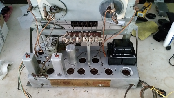
OK, enough blathering on. Pictures are more fun anyway. Here is the chassis as it sat on the bench this morning - almost all cleaned up, with just a few areas to tackle, and the decision whether or not to pull the tuning condenser for a proper clean.

I don't hold with furniture that talks.
Posts: 1,275
Threads: 44
Joined: Nov 2017
City: Menlo Park
State, Province, Country: CA
I have decided to attempt restuffing the multi-section cap. Since this is all for fun with no deadline to meet, it adds to the journey. Parts ordered - elsewhere on the Phorum I picked up on the long tall Nichicon series caps. Perfect for this task 
It will be interesting to see how this set compares to the Philco 16X console on the air. One thing is for certain, it weighs a lot less, despite their similarity in size. The cabinet is lighter, and the chassis has nowhere near the size and number of transformer and choke cores.
Cheers
Ed
I don't hold with furniture that talks.
Posts: 4,611
Threads: 51
Joined: Sep 2008
City: Sandwick, BC, CA
On local stations you probably would not notice a substantial difference, though the 16X has a somewhat more powerful audio amp. But in terms of shortwave and long distance AM broadcast band there will be a noticeable difference, the 16X has a tuned RF amplifier stage, a second IF amplifier stage, variable IF bandwidth, and a larger spread in the shortwave bands, which means that it will be more sensitive, and selective. I'm surprised that they didn't throw a magic eye tube into this set, RCA seemed to like throwing those into cheap five tubers just to market them as six tube sets, this has ten, but then again they were probably trying to market it as being Hi-Fi since the focus seems to have been on the audio amp and not the front end.
Getting back to the pushbutton bank, I would not be concerned about the vinyl insulation melting off from tube heat, the rubber (or gutta percha) probably melted because they didn't vulcanize it properly, this set has more then enough ventilation above the chassis to prevent such things, unless the wire was sitting 1/2 inch above the power output tubes.
Regards
Arran
(This post was last modified: 04-10-2018, 11:27 PM by Arran.)
Posts: 1,275
Threads: 44
Joined: Nov 2017
City: Menlo Park
State, Province, Country: CA
I have to admit, my "money" is on the Philco, but 1934 to 1941 represents a lot of development in valve technology and perhaps circuit design. There are fewer valves in the RCA front end, but then the oscillator is combined with the mixer. Then again, one valve is used in the RCA simply as a phase inverter for the push-pull output, whereas the 16X has one valved dedicated to the QAVC feature - not really contributing to reception.
It is interesting to compare the designs as seen by the user. I do like the arrangement of the 5 band coverage of the Philco, and the 2 speed tuning mechanism is really good - it was marketed specifically as an "All Wave" receiver, and from what I have seen and heard, it can definitely live up to the claim. Lack of a tuning indicator on the RCA is a surprise, and I think I've seen similar models that do include them, suggesting that the 110K was not top of the line. Its SW coverage is quirky by comparison. I'm fortunate enough to own both 
Another point about the melted insulation - The worst drips on the chassis were not from the wires nearest to valves. the only component nearby is the PSU filter cap... This says more about the previous restoration!
I don't hold with furniture that talks.
Posts: 1,275
Threads: 44
Joined: Nov 2017
City: Menlo Park
State, Province, Country: CA
Back to the bench today. I decided to remove the tuning capacitor and give it a proper service. Two fiddly connections beneath the chassis to the waveband switch, and the earth straps on top. Cleaned, thoroughly dried it and regreased all the bearings - smooth as silk. Cleaned the remaining bit of chassis where the capacitor lives, and then re-installed.
Oh, and I made an "upside down" chassis stand from scrap wood. Now I can turn it over safely to work on all the underside jobs.
Cheers
Ed
I don't hold with furniture that talks.
Posts: 1,275
Threads: 44
Joined: Nov 2017
City: Menlo Park
State, Province, Country: CA
Today saw the first serious work on the circuitry. Thought I would start on a few caps around the output stage. This soon descended into replacing short runs of wiring, as the rubber insulation of the original would tolerate nothing. This was fiddly and frustrating, and also revealed the cut ends and clipped leads of a number of repairs over the years. One paper cap was simply clipped at one end, and a disc type soldered across the valve socket to replace it. Time to tidy up 
Lots of out of tolerance reistors too, many of which are possibly replacements themselves.
I did find that my stock of film caps is in good order, and should furnish most, if not all the required parts to replace the paper parts.
Quite a bit more work in this one than I anticipated.
Cheers
Ed
I don't hold with furniture that talks.
Users browsing this thread: 1 Guest(s)
|
 . I might choose to detail the gold paint inlay on these.


