Posts: 3,102
Threads: 54
Joined: Apr 2011
City: Lexington, KY
Yeah, that would be best to just gut and then install new resistors in the original can or some under chassis if all won't fit in the can.
Very nice job so far Mike!
John KK4ZLF
Lexington, KY
"illegitimis non carborundum"
Posts: 15,304
Threads: 532
Joined: Oct 2011
City: Jackson, NJ
John
The resistor got desoldered, unsoldered from chassis (had to put the iron at 850F), unscrewed and removed. Now I will solder the wires back, see if it still hums.
Sad thing is, it is right on the money value-wise.
The dissipated power is quite large, each of the 970 ohm sections dissipates 3W plus 0.5W the 87ohm section. 7W has to be vented out somehow, plus the sheer size of the 10W resistors. I will try to get them back into the Candohm shell.
While out of circuit, it exhibits absolutely no leakage.
People who do not drink, do not smoke, do not eat red meat will one day feel really stupid lying there and dying from nothing.
(This post was last modified: 04-22-2019, 09:51 PM by morzh.)
Posts: 15,304
Threads: 532
Joined: Oct 2011
City: Jackson, NJ
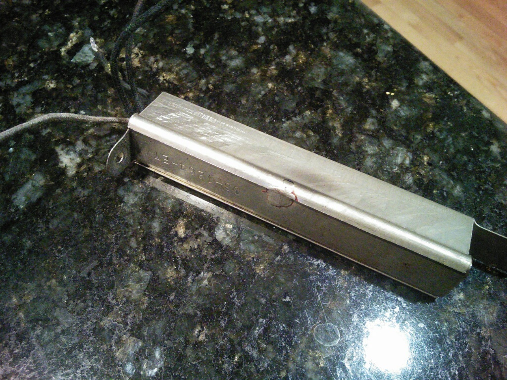
Here it is.

The theory proved correct, the Candom leaks the potential to the case.
Once taken off and then soldered without touching the chassis, the hum stops completely.
The case measures 123V to chassis which indicates that the leakage occurs right at the top lead where it is 125V.
I am going to completely open it to look for obvious reasons, and if not found, I will replace it.
The problem is, the main wall and the screw hole are actually the Candohm itself so there is no complete box to restuff.
People who do not drink, do not smoke, do not eat red meat will one day feel really stupid lying there and dying from nothing.
Posts: 15,304
Threads: 532
Joined: Oct 2011
City: Jackson, NJ
I ordered two 10W 1K resistors (Have an 82 Ohm one).
Anyone could think of a good way to securing them inside the old shell? The insulation should withstand high temperature as the dissipation will be 6W inside it.
I will also attempt to bake the original Candohm to see if this would cure the leakage.
PS. Baked the Candohm for 2 hrs at 212F. The leakage I saw when I took it out (it behaved as a cap, started at 30k and kept going up into hundreds) became tens of Megohms.
Will try to solder in and see if it still imparts the voltage.
People who do not drink, do not smoke, do not eat red meat will one day feel really stupid lying there and dying from nothing.
(This post was last modified: 04-25-2019, 09:23 AM by morzh.)
Posts: 15,304
Threads: 532
Joined: Oct 2011
City: Jackson, NJ
So, I tried the baked Candohm in circuit. Connected the case to the chassis.
The hum is almost gone.
However the leaking voltage is still there, but the leakage current is 0.2mA instead of 10mA as before when loaded with 10kOhm resistor.
Honestly, if I got it in this condition I would never look into this in the first place.
However, I think I will rebuild it. I already got the resistors.
People who do not drink, do not smoke, do not eat red meat will one day feel really stupid lying there and dying from nothing.
Posts: 15,304
Threads: 532
Joined: Oct 2011
City: Jackson, NJ
Today took one last shot at baking the Candohm.
Baked it at 250F for 4hrs.
It is interesting, the leakage resistance decreased from a few MOhms to 250kOhm but this holds steady. When in-circuit, the hum is still very low, and the voltage now is about 8V.
But every minute or so there's a pop (not loud, but audible) and the voltage jumps to 30-40V a d quickly returns to 8V.
Probably a breakdown.
So.....the rebuilding is still the best option, but need to build the base, or else to use the Candohm for which it needs to be gutted.
PS. Gutted it. Was trying to extract the resistor intact, but broke the 86 Ohm piece off. The two 970 ohm sections are fine. Could be re-used actually.
The old fishpaper was crumbling; no wonder it leaked.
I can actually re-wrap it in the new fishpaper, though I'm not sure what temperature it would withstand.
People who do not drink, do not smoke, do not eat red meat will one day feel really stupid lying there and dying from nothing.
(This post was last modified: 04-28-2019, 07:24 PM by morzh.)
Posts: 289
Threads: 42
Joined: Jan 2014
City: Jeffersonville
State, Province, Country: PA
Hi Mike - I might have a spare body. If I can find do you want it?
Thanks,
Paul
Posts: 15,304
Threads: 532
Joined: Oct 2011
City: Jackson, NJ
Paul
Thanks. Spare body of the Candohm?
People who do not drink, do not smoke, do not eat red meat will one day feel really stupid lying there and dying from nothing.
Posts: 15,304
Threads: 532
Joined: Oct 2011
City: Jackson, NJ
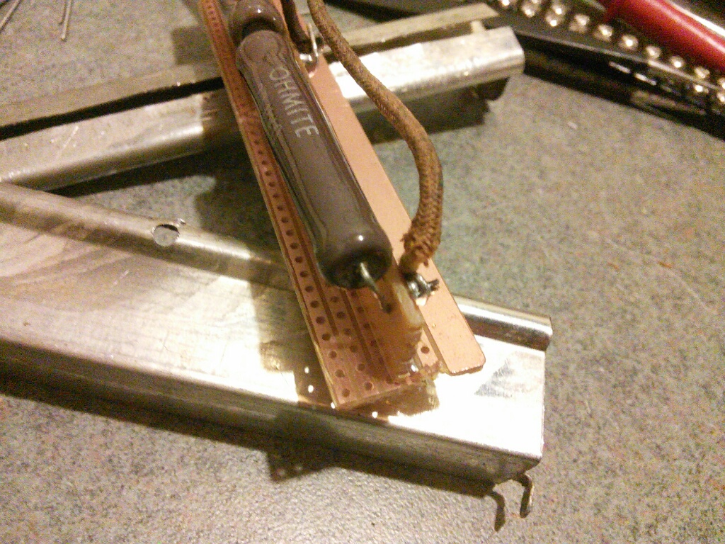
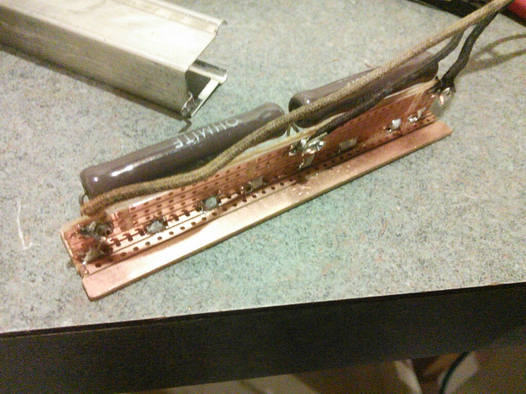
So I restuffed the Candohm. Two 10W 1K resistors.
Like so:


So far so good: no hum, no pops....
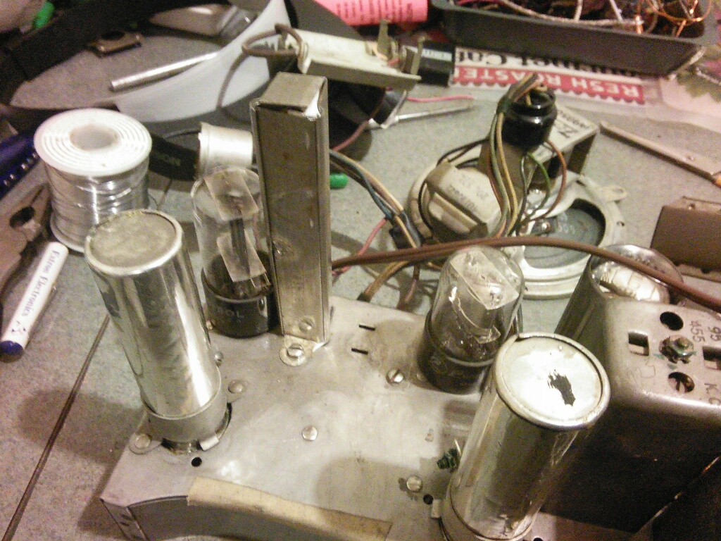
The 86 ohm resistor that dissipates mere 1/2W went under the chassis. It isn't hot as it is 5W resistor so isn't dangerous for surrounding wires.
Now to alignment.
People who do not drink, do not smoke, do not eat red meat will one day feel really stupid lying there and dying from nothing.
(This post was last modified: 04-30-2019, 08:27 PM by morzh.)
Posts: 1,275
Threads: 44
Joined: Nov 2017
City: Menlo Park
State, Province, Country: CA
Nice work! When you mentioned restuffing the Candohm, I did not realise this one had a larger section, with some room for new components.
I don't hold with furniture that talks.
Posts: 289
Threads: 42
Joined: Jan 2014
City: Jeffersonville
State, Province, Country: PA
Sorry Mike, I misread your post and thought you needed the candoholm body. Obviously not.
Thanks,
Paul
Posts: 15,304
Threads: 532
Joined: Oct 2011
City: Jackson, NJ
Paul
Thanks anyway, mighty nice of you.
Mike
People who do not drink, do not smoke, do not eat red meat will one day feel really stupid lying there and dying from nothing.
Posts: 3,102
Threads: 54
Joined: Apr 2011
City: Lexington, KY
Looking good Mike 
John KK4ZLF
Lexington, KY
"illegitimis non carborundum"
Posts: 15,304
Threads: 532
Joined: Oct 2011
City: Jackson, NJ
Gave it the alignment yesterday. The whole week I was nursing a sore throat and nose cold, and even though it never gets really bad with me (this one is the worst in about 7 years, usually goes in two days with some nasal burning) it kept me from sleeping (I tend not to get drugs for this) and so I was pretty exhausted so I could find it in myself to go to the basement only yesterday.
Before I got to alignment I tried to investigate why my tuning cap is scratchy in the last 1/3 before being fully meshed. I washed it in the beginning of the restoration, dried it; then I tried to see if there are micro-shorts by holding the meter between the plates - no result, no shorts in all three sections whatsoever.
Tried to change tubes in case it is some reaction - no effect; tried to wiggle tubes and wires.....anywho, in the end I realized the scratchy noise only pronounced on BC band at the last 1/2-1/4 of the dial before fully meshed, and on SW scales it is barely noticeable or not there at all.
So I gave up.
The IF was pretty close, it showed up as soon as I applied it to the mixer, though the signal went up quite a bit after I aligned all the trimmers.
BC band alignment is really dependent on the mutual positioning of the WaveMagnet ribbon cable and the WaveRod holding fixture and it affects the 1400kHz positioning. I was able to get pretty close the third time when I realized it and separated the fixture and the wavemagnet ribbon cable.
The SW bands aligned pretty well; all were off, but within the scale, except 19M one which I thought was bad, but then found out it was OK, just couldn't find it.
First it is done with the Waverod; Then the same is done with the Wavemagnet.
The Wavemagnet alignment using the trimmers in it is very.....approximate. Including the fact that some caps do not affect much the alignment they are said to adjusted for, but then affecting the others. Nevertheless it receives just fine.
I think I will put it together now. There is still the desire to change the dial cover which is a bit yellowish, but maybe later. It is not too bad.
The battery has been assembled so I could use it now.
People who do not drink, do not smoke, do not eat red meat will one day feel really stupid lying there and dying from nothing.
Posts: 1,475
Threads: 69
Joined: Nov 2012
City: Kansas city, MO.
I've been following your thread all along Mike. Great job on the restoration.
Mark Palmquist at Retro Radio Repair I believe has the dial cover you need if you decide to change it.
Users browsing this thread: 1 Guest(s)
|


