Posts: 1,181
Threads: 48
Joined: Oct 2017
City: Allendale, MI
What's in your power transformer?
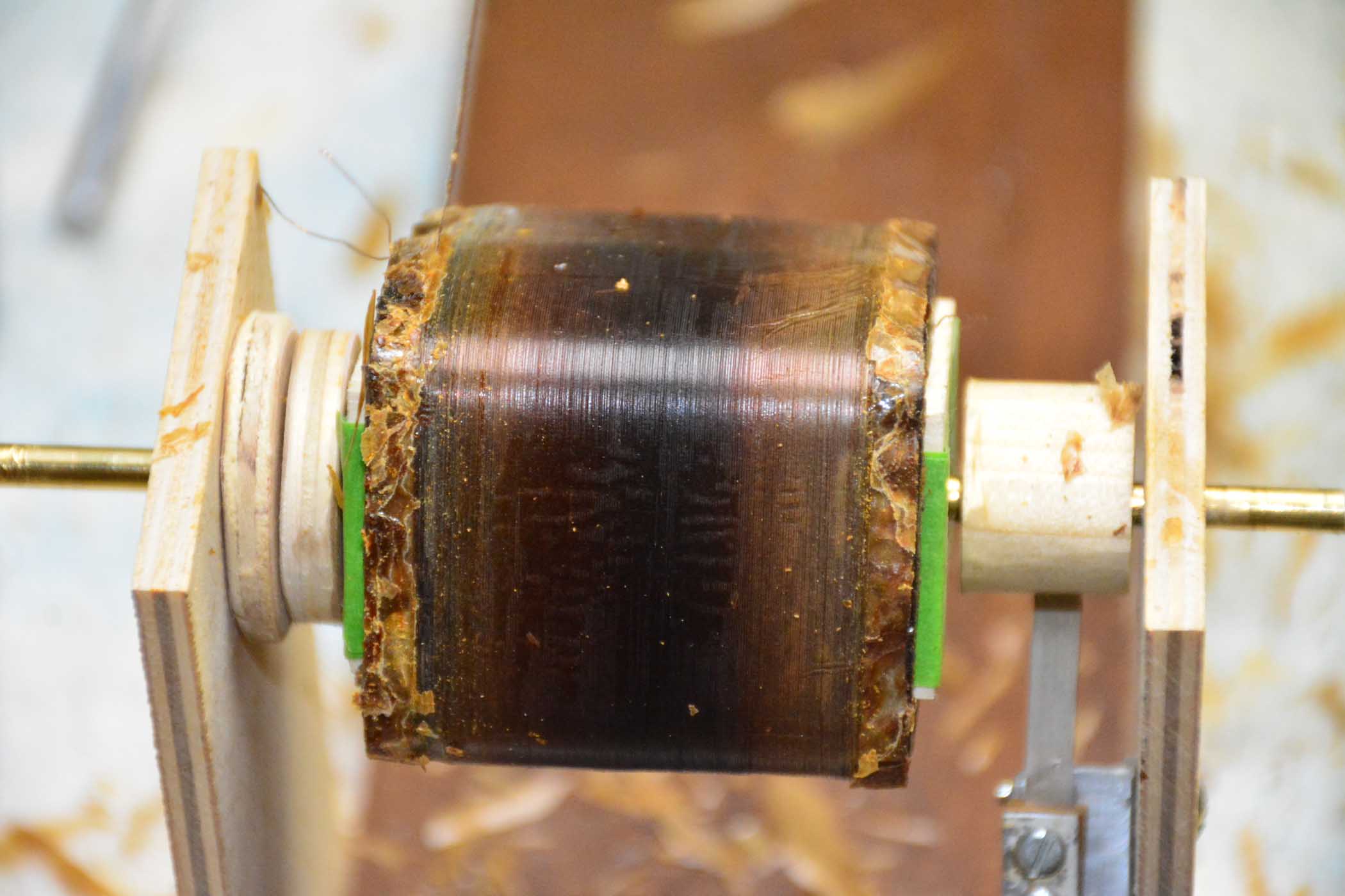
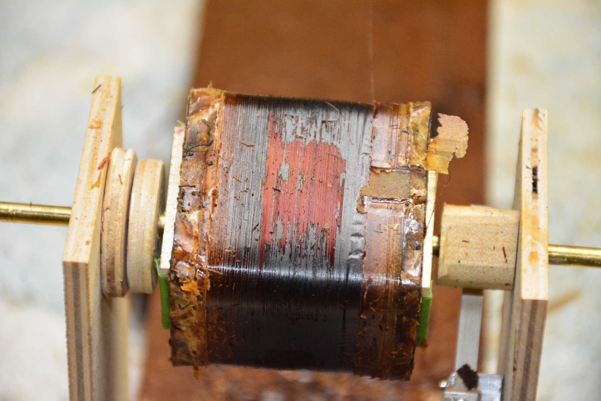
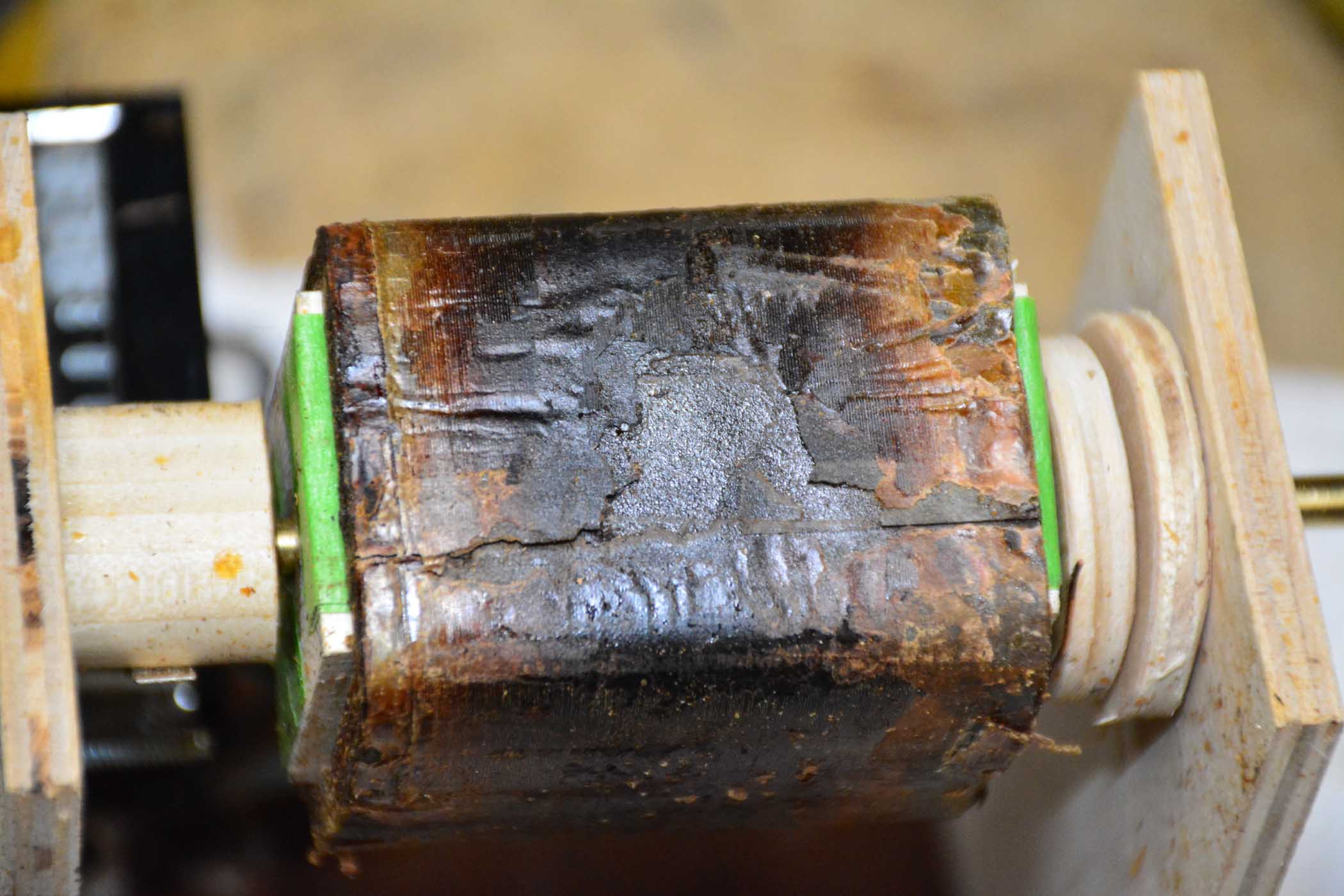
I presume this damage is from running the radio with bad caps, but don't know for sure. I hope it's not typical of old transformers in these old radios.
Posts: 1,181
Threads: 48
Joined: Oct 2017
City: Allendale, MI
So, after seeing the HV windings of the transformer as shown in the last post, I'm glad I took the decision to rewind. Here are some photos:
Primary winding:
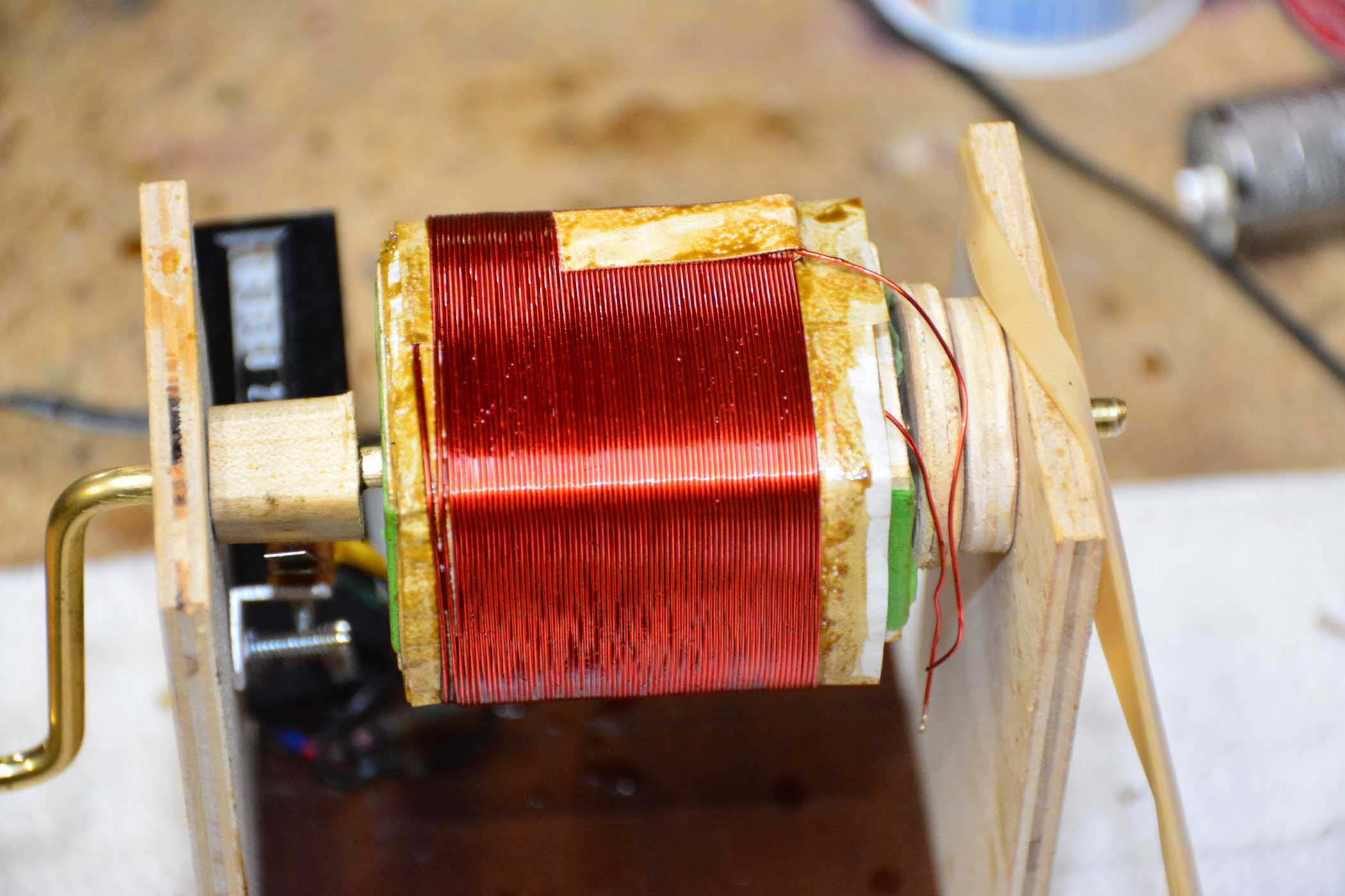
Center tap of final filament winding for most of the tubes. 10 turns of parallel 14 AWG wire.
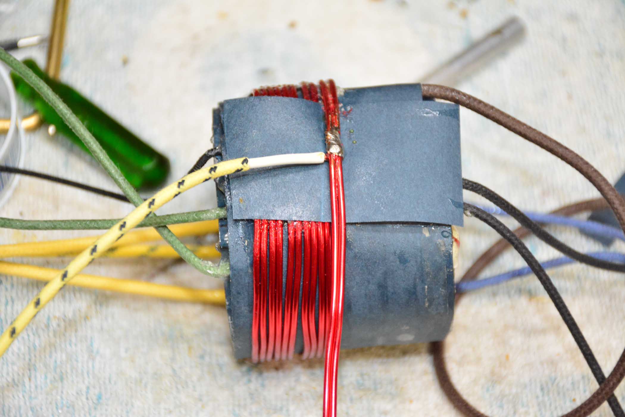
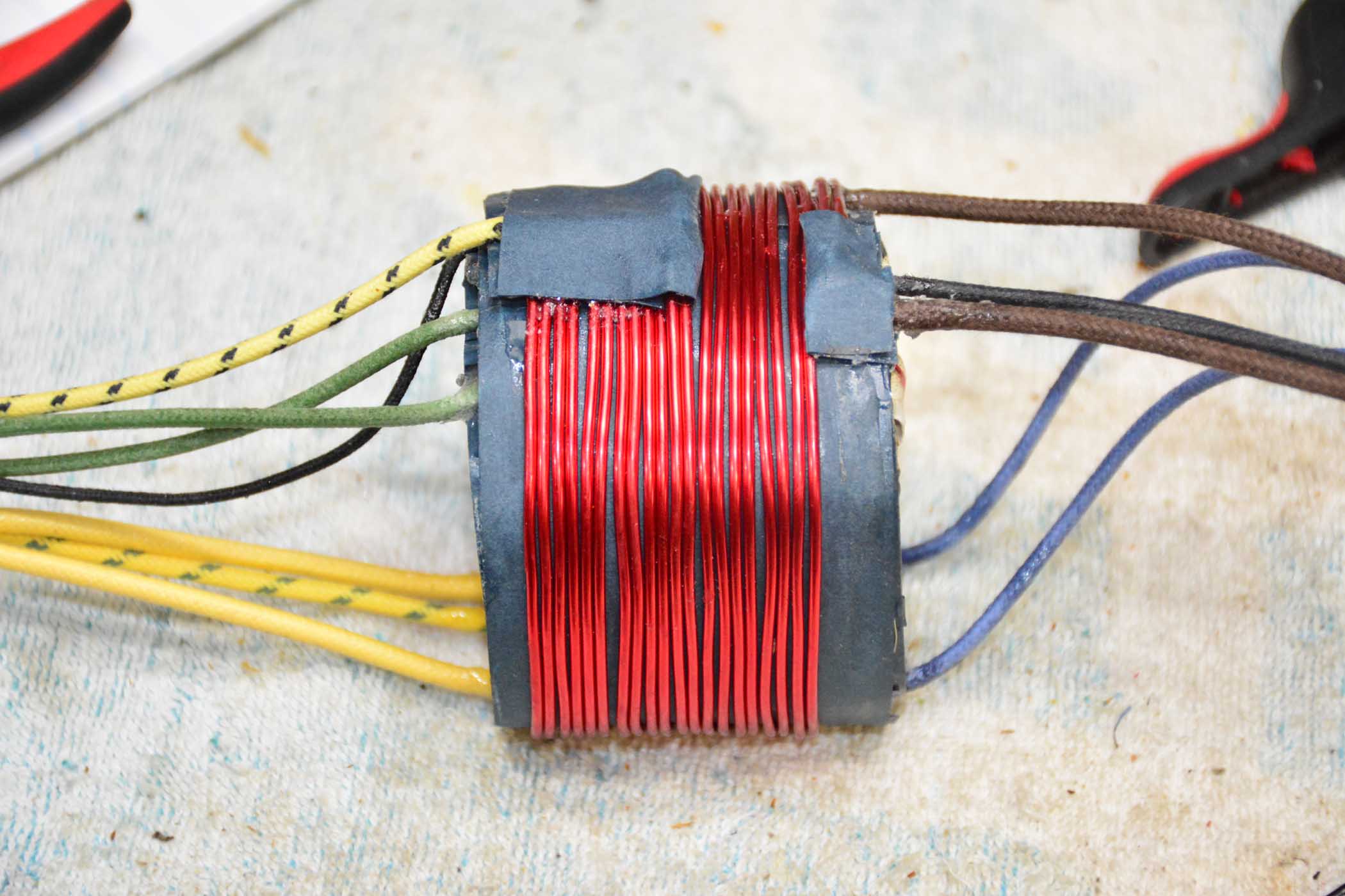
All windings finished:
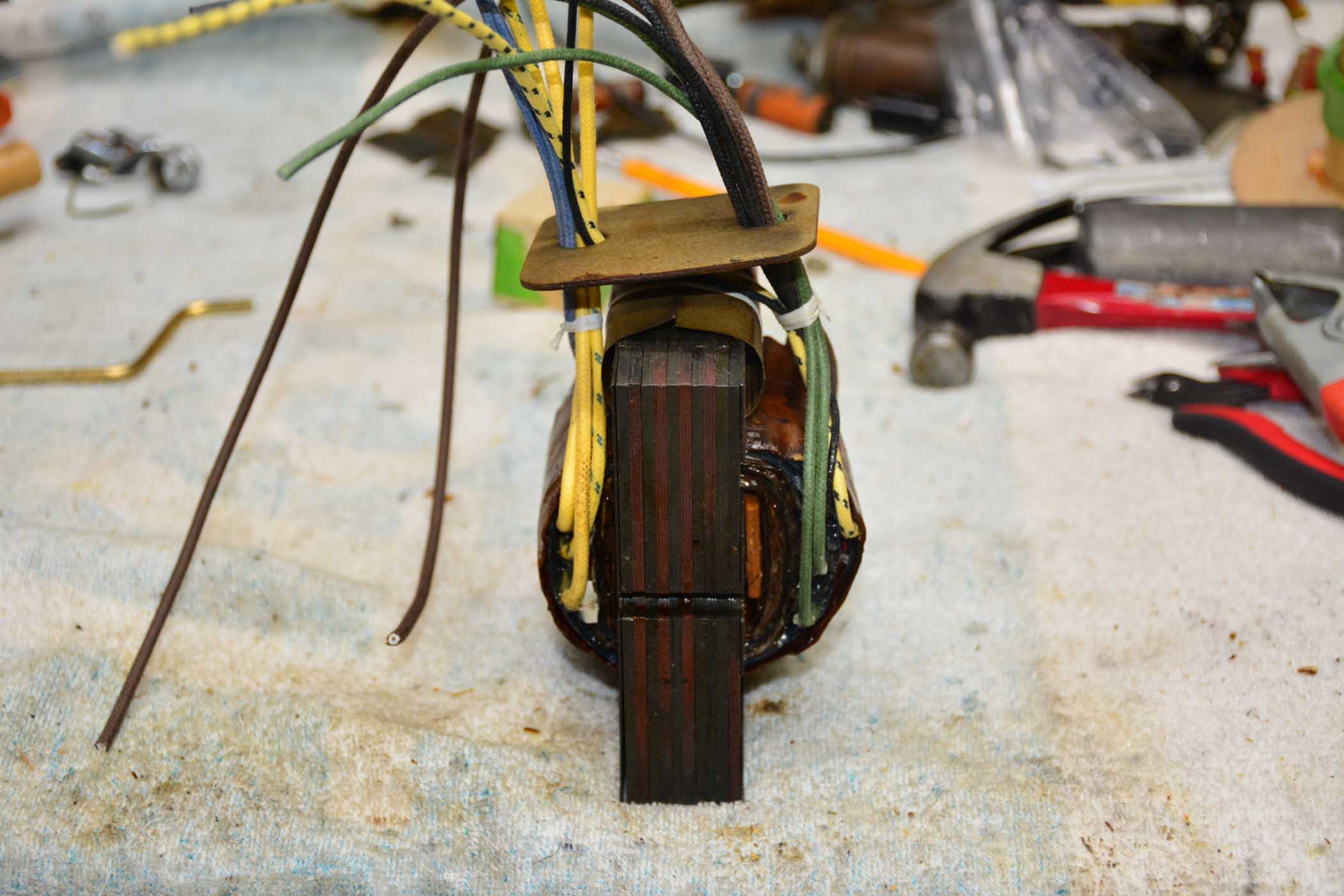
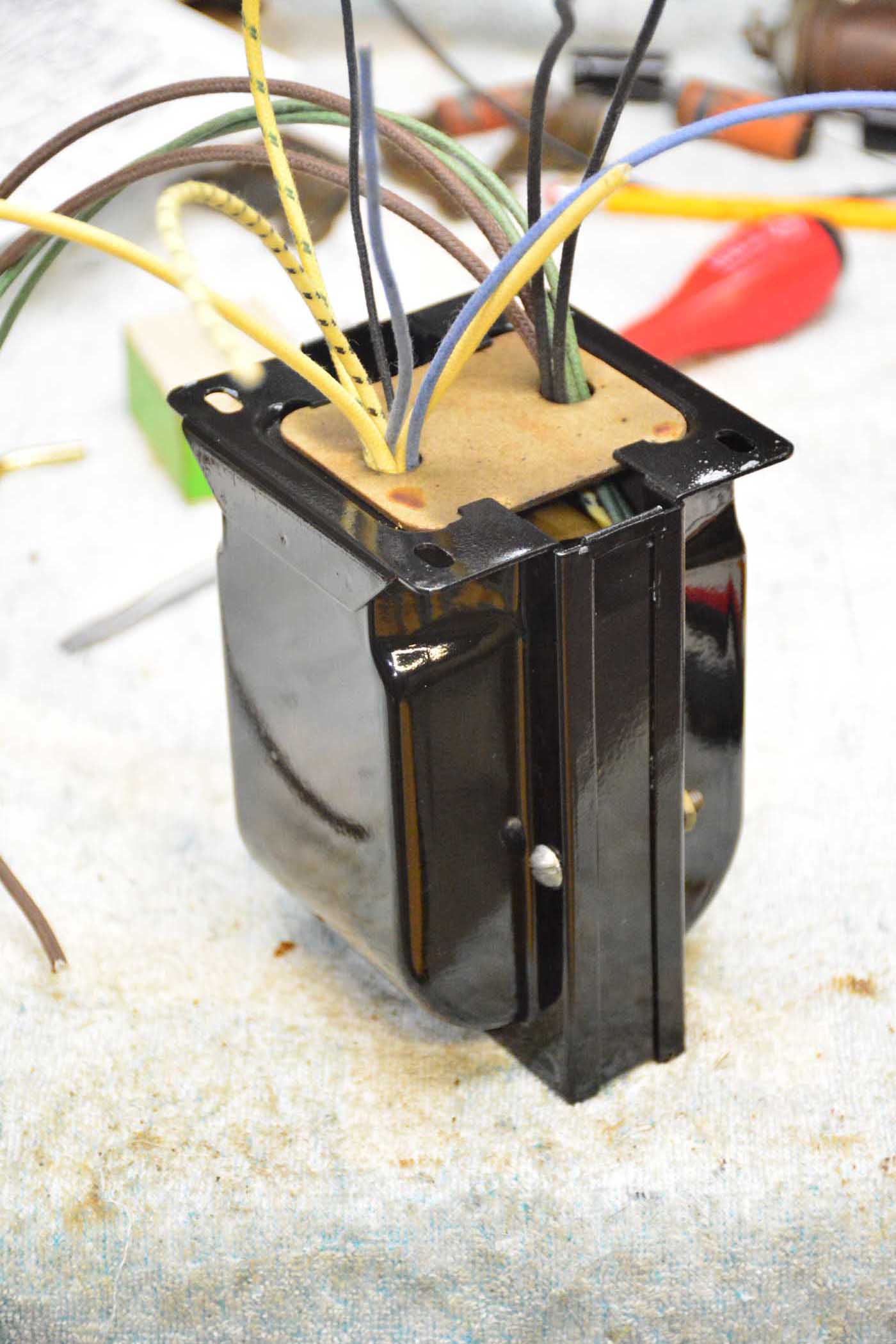
Re-assembly. Core was re-assembled, clamped together, then heated to re-melt the wax to hold the lamination tightly together.
Posts: 2,118
Threads: 112
Joined: Jun 2010
City: Medford OR (OR what?)
How are your voltages?
Yes, yours got hot. Most common issue is bad filters, but what I have also seen is low or missing bias on an output tube. Amazing that they can conduct enough current to cause the PT to overheat, but tubes like a 42 (6F6) can.
"I just might turn into smoke, but I feel fine"
http://www.russoldradios.com/
Posts: 1,181
Threads: 48
Joined: Oct 2017
City: Allendale, MI
Voltages are good. Should work fine.
Posts: 189
Threads: 22
Joined: Aug 2018
City: Kewanee
State, Province, Country: Illinois
VERY NICE work. Very impressive! Great job!
1929 Victor R-32, 1933 60L, Phil 40-158, Phil 42-400X, Phil 47-1230 Radio/Phono,, 1950 Phil TV t-1104, Air King 4000, Philco 41-105, Philco 37-675, RCA Victor 9K2, PT-50, Phil 54C, PT-44 Cabinet, Phil 118X Cabinet
Gregg 
Posts: 816
Threads: 25
Joined: Mar 2014
City: Louisville, KY
Wish you'd begun your pic-taking sooner.
How do you know how many turns to wind, which winding to start, what to wind it on, why to double the filament windings, what size wire, etc, etc, etc, . . .
Posts: 1,181
Threads: 48
Joined: Oct 2017
City: Allendale, MI
Jake, I'll try to answer your questions! I took the transformer apart by removing the laminatons for the core, then removing the outside wrapping that had the part number on it. I saved that to put back on the rewound PT to make it look original. Each layer was then unwound, the wire diameter measured, and the number of turns counted as they were unwound, taking note of exactly how they were wound (ending point, starting point, # of layers, and # of turns per layer - which does vary from layer to layer.) # of turns per layer is not critical so long as the total number of turns is correct. # of layers and the thicknes of the paper separating them is critical as you don't want to wind up with the bobbin so thick that you cannot slide the E laminations back into the bobbin (I reuse the original bobbin form). Rewinding is just the unwinding in reverse. Each layer is separated by a strip of paper and the windings for a completed layer are held in place with a coating of shellac that I use a heat gun on to get it to dry more quickly. Getting the wire to lay perfectly is a bit tedious but not too bad if you use some form of wire winding contraption. It takes some patience and practice. All in all, it is not difficult, just very tedious and time consuming.
The final layer is the power for the filaments of 5 tubes: 4 24's and 1 27. These are 2.5 volt filaments and draw 1.75 amps per tube. That's almost 9 amps. I think they doubled the 14 AWG wire to increase current handling capacity without adding thickness to the bobbin. In reality, 10 turns of a single wire of 14 AWG would handle the 9 amps, but perhaps they wanted to prevent any heat from being generated in that winding.
I took a couple of liberties in the number of turns in the primary and HV secondary. I increased the # of turns in the primary by 10 turns. This increases the voltage to the 2.5 volt filaments to 2.75 volts and to the rectifier filament from 5 volts to 5.5 volts. Though this might shorten the life of a tube ever so slightly, it should increase cathode emissions slightly on the weak tubes that will probably be used. This necessitated that the HV secondary # of windings be increased by about 150 turns to achieve the stated 700 volt output. Actual voltage measurements bear out the calculations. Ultimate results will be determined when the radio is complete!
Hope this answers your questions!
Posts: 1,393
Threads: 69
Joined: Oct 2007
City: Linn Creek, MO
Increasing the number of turns in the primary will decrease the voltage in all the secondaries. You have compensated for that in the HV but the filament voltages will be low.
Steve
M R Radios C M Tubes
Posts: 816
Threads: 25
Joined: Mar 2014
City: Louisville, KY
rfeenstra ,
Thanks for your extended reply ! So you have to count all that as you are unwinding!
You have a winding mechanism and you re-use a bobbin from the transformer. That answers a number of my questions. More later. 
(This post was last modified: 04-29-2019, 06:02 AM by Jake Blake.
Edit Reason: Add addressee
)
Posts: 1,181
Threads: 48
Joined: Oct 2017
City: Allendale, MI
Steve, you are correct. I confused myself! Calculations at 1:00 in the morning.... Yet my output voltage for the filaments are as I listed them. Therefore, the original filament voltages must have been higher yet, perhaps compensating for internal resistance losses. My tubes will run cooler and last longer, but weak tubes will be less effective. Oh well, best laid plans...
Posts: 1,181
Threads: 48
Joined: Oct 2017
City: Allendale, MI
For grins and giggles, I installed the tubes (except the 80) and powered up using a variac to check filament voltages. At slightly lower than line voltage, I measure 2.52 volts on the 24's and 27, 2.7 on the 42, and 5.5 on the 80 without the tube. I'm good!
Posts: 7,212
Threads: 266
Joined: Dec 2009
City: Roslyn Pa
Sounds good! I think you mean a #47.
When my pals were reading comic books
I was down in the basement in my dad's
workshop. Perusing his Sam's Photofoacts
Vol 1-50 admiring the old set and trying to
figure out what all those squiggly meant.
Circa 1966
Now I think I've got!
Terry
Posts: 1,393
Threads: 69
Joined: Oct 2007
City: Linn Creek, MO
With todays higher line voltages, a few extra turns on the primary is probably a good thing.
Steve
M R Radios C M Tubes
Posts: 2,118
Threads: 112
Joined: Jun 2010
City: Medford OR (OR what?)
You can also get a close approximation of turns, or actually wire length by cutting off the windings, say for the HV, and then weigh them. You will need to know the gauge of the original wire and use that ga. for the replacement. This is far easier than counting what might be hundreds of turns. You need a good , accurate scale.
"I just might turn into smoke, but I feel fine"
http://www.russoldradios.com/
Posts: 816
Threads: 25
Joined: Mar 2014
City: Louisville, KY
"With todays higher line voltages, a few extra turns on the primary is probably a good thing."
Yes, I thought that also.
Users browsing this thread: 1 Guest(s)
|


